Method and apparatus for suppressing corrosion of carbon steel, method for suppressing deposit of radionuclide onto carbon steel members composing a nuclear power plant, and film formation apparatus

a nuclear power plant and carbon steel technology, applied in nuclear engineering, emergency protection arrangements, nuclear elements, etc., can solve the problems of increasing the radioactive waste of the condensate purification apparatus, the inability of the plant and the inability to suppress the corrosion of metals. , to achieve the effect of suppressing the corrosion of carbon steel members and effectively suppressing the deposit of radionuclides

Inactive Publication Date: 2009-11-26
NAGASE MAKOTO +5
View PDF3 Cites 6 Cited by
  • Summary
  • Abstract
  • Description
  • Claims
  • Application Information

AI Technical Summary

Benefits of technology

[0008]However, a conventional method of injecting oxygen to feed water of the power generation plant cannot suppress corrosion of metals when oxygen injection is stopped and must keep on injecting oxygen during the operation of the power generation plant. This method runs contrary to the recent plant tendency that keeps the in-reactor environment in the reducing status in order to suppress stress corrosion cracking of the stainless steel structure members.
[0009]Similarly, another conventional method (e.g. Japanese Patent Laid-open No. 2000-292589) of adding chemicals to feed water of the nuclear power plant to control pH of the reactor water to greater than 7 is forced to keep on feeding chemicals during the operation of the nuclear power plant. Further, since the added chemicals increase the load of the condensate purifying apparatus, the radioactive wastes from the condensate purifying apparatus may increase. Accordingly, it is desired to suppress corrosion of carbon steel members that constitute the nuclear power plant.

Problems solved by technology

However, a conventional method of injecting oxygen to feed water of the power generation plant cannot suppress corrosion of metals when oxygen injection is stopped and must keep on injecting oxygen during the operation of the power generation plant.
Further, since the added chemicals increase the load of the condensate purifying apparatus, the radioactive wastes from the condensate purifying apparatus may increase.
Sho 58(1983)-79196 that injects the metal ions such as zinc into the reactor water has problems that injection of zinc ions must be always continued to the reactor water during the operation of the nuclear power plant, that depleted zinc must be used to avoid zinc itself being activated, and that these requirements push up the power generation cost.
This method cannot be formed oxide films on low-temperature surfaces of the reactor water purifying system and the carbon steel pipes of the residual heat removal system except for the high-temperature surface of the reactor water purifying system.
Further, just after the nuclear power plant starts to operate for example, after chemical decontamination, radionuclide are inevitably contained also in the reactor water being used for formation of oxide films.

Method used


Image

  • Method and apparatus for suppressing corrosion of carbon steel, method for suppressing deposit of radionuclide onto carbon steel members composing a nuclear power plant, and film formation apparatus
  • Method and apparatus for suppressing corrosion of carbon steel, method for suppressing deposit of radionuclide onto carbon steel members composing a nuclear power plant, and film formation apparatus
  • Method and apparatus for suppressing corrosion of carbon steel, method for suppressing deposit of radionuclide onto carbon steel members composing a nuclear power plant, and film formation apparatus

Examples


embodiment 1

[0079]FIG. 6 is a flow chart showing a method for suppressing corrosion of carbon steel of an embodiment 1 which is one preferred embodiment of the present invention. FIG. 7 is an explanatory drawing showing the connection of a film formation apparatus to the feed water pipe of the BWR plant when the method of suppressing corrosion of carbon steel members of FIG. 6 is applied to the feed water of the BWR plant. FIG. 8 is a detailed structural diagram showing the film formation apparatus of FIG. 7.

[0080]As shown in FIG. 7, the BWR plant comprises a reactor 1 having a reactor pressure vessel loading a plurality of fuel assemblies filled with nuclear fuel materials which generates nuclear fission, a main steam pipe 2 connected to the reactor 1, a steam turbine 3 connected to the main steam pipe 2, and a condenser 4 connected to the steam outlet of steam turbine 3. Steam generated in the reactor is supplied to the steam turbine 3. The steam exhausted from the steam turbine 3 is condense...

embodiment 2

[0108]Embodiment 2 is different from Embodiment 1 in that Embodiment 2 forms nickel ferrite films and Embodiment 1 forms the magnetite films.

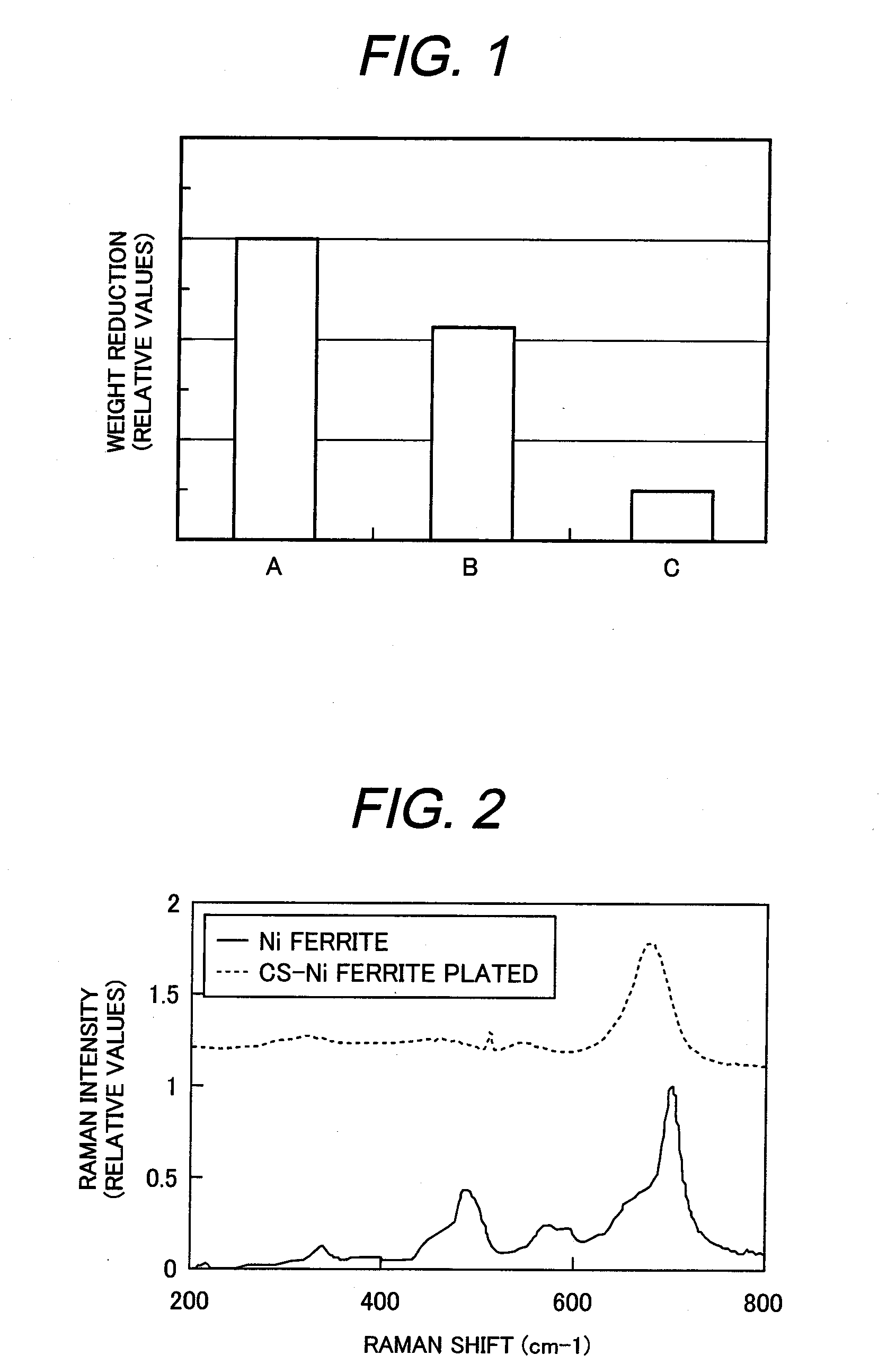
[0109]Aforesaid Embodiment 1 describes the procedure and the apparatus to form the magnetite film on the inner surface of the carbon steel pipes of the feed water system. In the result (see FIG. 1) of a test of dipping samples in pure water at ordinary temperature, both magnetite and nickel ferrite films can obtain almost the same corrosion suppressing effect. However, in the actual service environment of the feed water system which uses pure water at high temperature, the nickel ferrite films have longer corrosion suppressing effect than the magnetite films because the solubility of the nickel ferrite is less than that of the magnetite. The embodiment 2 forms the nickel ferrite film on the surface of wetted surfaces of the carbon steel members composing the nuclear power plant.

[0110]FIG. 9 shows a method of suppressing corrosion of carbon stee...

embodiment 3

[0114]Embodiment 3 is different from Embodiment 1 in that Embodiment 3 connects the film formation apparatus 30 to the feed water pipe 10 of the secondary system of a PWR plant but Embodiment 1 connects the film formation apparatus 30 to the feed water pipe 10 of the BWR plant. FIG. 11 is a structural diagram showing Embodiment 3 that connects the film formation apparatus 30 to the feed water pipe in the secondary system of the PWR plant. FIG. 11 shows only the secondary system including a steam generator 69 but does not contain the configuration of a primary system of the PWR plant.

[0115]Embodiment 3 is different from Embodiment 1 (for example, FIG. 7) in that a deaerator 70 is provided with the feed water pipe 10 between the low pressure feed water heater 8 and the high pressure feed water heater 9. The deaerator 70 is used to remove gas components from the feed water. Embodiment 3 is similar to Embodiments 1 and 2 as for a method of connecting the film formation apparatus 30 to t...


PUM

PropertyMeasurementUnit
temperatureaaaaaaaaaa
pHaaaaaaaaaa

Abstract

The present invention is a method for suppressing corrosion of carbon steel members composing a nuclear power plant. That is, the processing solution contains a chemical including iron (II) ions, an oxidizing agent for oxidizing at least one part of the iron (II) ions into iron (III) ion, and a pH adjustment agent for adjusting pH. The pH of the processing solution is adjusted in the range of 5.5 to 9.0 by the pH adjustment agent. The processing solution is introduced into a purifying system pipe having the carbon steel members. The iron (II) ions are adsorbed on an inner surface of the purifying system pipe, namely, a surface of the carbon steel members. The ferrite film is formed on the surface of the carbon steel members by oxidizing the absorbed iron (II) ions. Therefore, corrosion of the carbon steel members is suppressed by the ferrite film.

Description

BACKGROUND OF THE INVENTION[0001]The present invention relates to methods and apparatus for suppressing corrosion of carbon steel, method for suppressing deposit of radionuclide onto carbon steel members composing a nuclear power plant, and film formation apparatus.[0002]Well-known nuclear power generation plants are, for example, boiling water type power generation plant (hereinafter referred to as BWR plant) and pressurized water type power generation plant (hereinafter referred to as PWR plant). The BWR plant supplies feed water into with a reactor having a reactor pressure vessel in which a plurality of fuel assemblies are loaded, through a feed water system, and causes cooling water (coolant) to boil into steam. Almost all of the generated steam is supplied to a steam turbine to drive the steam turbine and a power generator connected to the turbine in order to generate electric power. The steam exhausted from the steam turbine is condensed into water by a condenser. The condens...

Claims


Application Information

Patent Timeline
Patent Type & Authority Applications(United States)
IPC IPC(8): C23F11/00
CPCC23C22/68
Inventor NAGASE, MAKOTOHOSOKAWA, HIDEYUKIMORISAWA, SATOSHISAKASHITA, MOTOAKIYOKOTA, KATSUOKATAOKA, IICHIRO
Owner NAGASE MAKOTO
Why Eureka
Try Eureka