
Systems, devices and methods for posterior lumbar interbody fusion

a lumbar interbody and fusion technology, applied in the field of spinal surgery, can solve the problems of substantial challenges in performing plif surgery, and achieve the effect of facilitating tissue cutting, facilitating tissue cutting, and facilitating tissue cutting

Inactive Publication Date: 2009-11-26
SPINEALIGN MEDICAL
View PDF24 Cites 82 Cited by
  • Summary
  • Abstract
  • Description
  • Claims
  • Application Information

AI Technical Summary

Benefits of technology

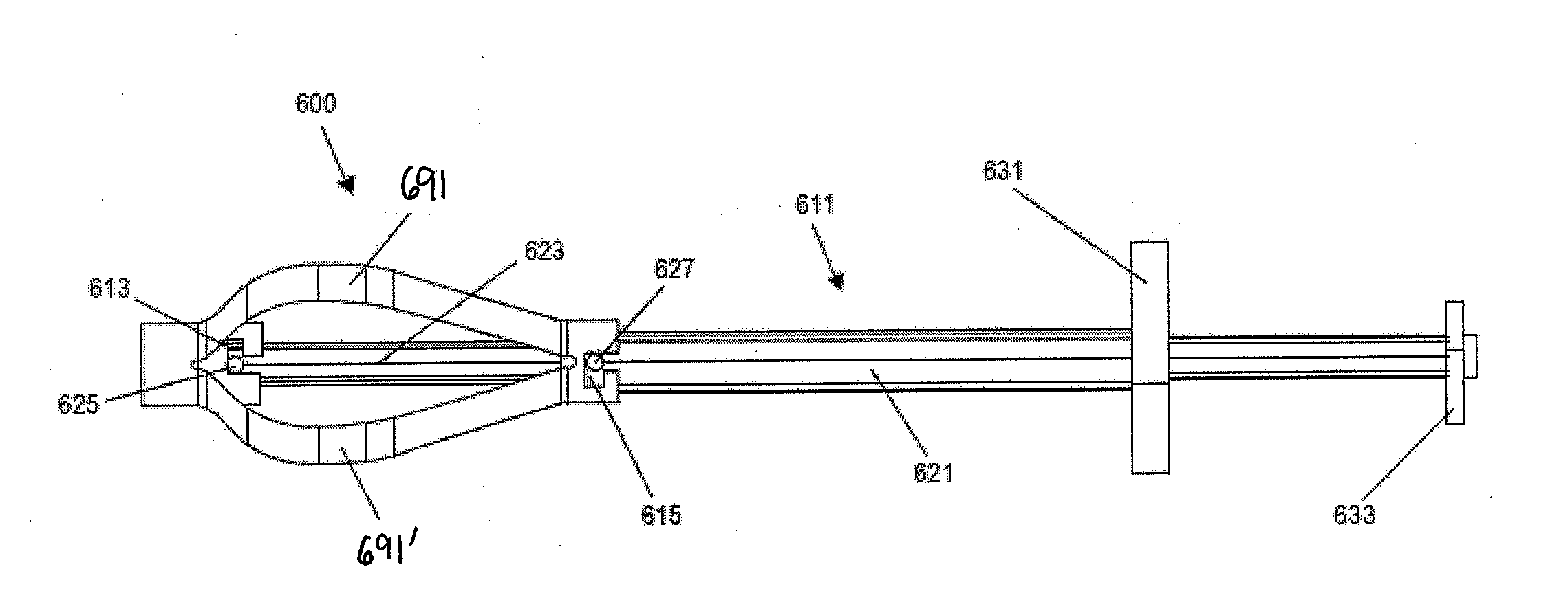
[0013]The stabilization device may be expanded within the body (e.g., within the disc and / or vertebra) so that the distal end is stable and does not move (e.g., to withdraw or advance laterally) as the device is allowed to expand. For example, the step of expanding may include holding the distal end of the stabilization device substantially fixed and allowing the proximal end of the stabilization device to foreshorten during expansion. Controlling the expansion in this manner may prevent the device from shifting during insertion, allowing predictable placement, and may also prevent damage to tissue.
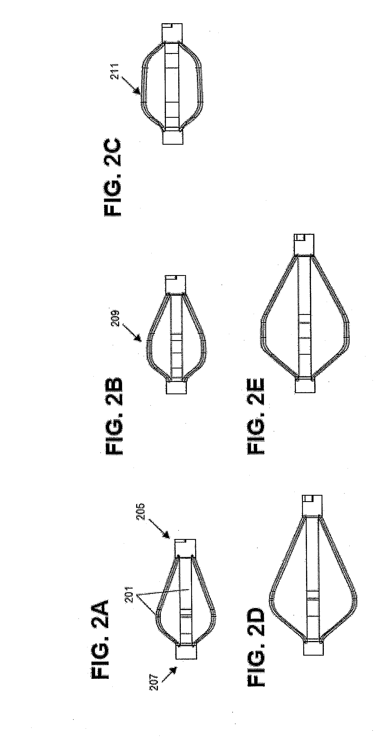
[0025]For example, in some variations, one or more struts on the implant are pre-based to have an expanded shape that is more abruptly curved than other struts on the same implant. Typically, the delivery configuration for each strut is relatively flat (e.g., parallel to the long axis of the implant), so that it can be delivered in a collapsed, elongate configuration. The struts are therefore pre-biased to an expanded (or mostly expanded) shape that extends from the elongate axis of the stabilization implant. The curvature of the expanded strut shape may help contribute to the ability of the struts to cut through the tissue or to support tissue (e.g., bone). The more extreme the curve of the strut, the more readily the strut may cut the tissue. Alternatively, the surface of the strut and / or the cross-sectional shape may be configured to more readily cut (e.g., sharper and / or thinner outward-facing surfaces) may more readily cut tissue, including bone, than flatter or thicker outward-facing strut surfaces).

Problems solved by technology

Thus, substantial challenges remain in performing PLIF surgeries.

Method used


Image

  • Systems, devices and methods for posterior lumbar interbody fusion
  • Systems, devices and methods for posterior lumbar interbody fusion
  • Systems, devices and methods for posterior lumbar interbody fusion

Examples


Embodiment Construction

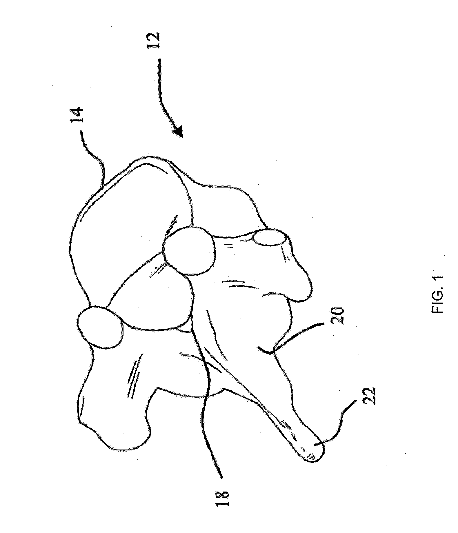
[0055]The stabilization devices, systems and methods described herein may aid in posterior lumbar interbody fusion (PLIF) surgeries. The stabilization devices (also referred to as simply “devices”) described herein may be implanted into an intervertebral disc and packed with a bone graft or biologic or synthetic material to promote anchoring of the stabilization device and fusion of the vertebrae adjacent to the intervertebral disc. The devices, systems and methods described herein may be used in any appropriate body region, particularly in the lower back or lumbar region of the spine.

[0056]In general, the stabilization devices described herein include a self-expanding elongate shaft that may be positioned within an intervertebral disc and / or within a vertebra and expanded to anchor within that portion of the spine. The elongate shaft may include a plurality of self-expanding struts that expand to form a bow-shape. The stabilization device may also typically include one or more atta...


PUM

PropertyMeasurementUnit
Lengthaaaaaaaaaa
Forceaaaaaaaaaa
Shape memory effectaaaaaaaaaa

Abstract

Described herein are stabilization devices, systems and methods to aid in posterior lumbar interbody fusion (PLIF) surgeries. The stabilization devices (“devices”) described herein are typically self-expanding devices that may be implanted into an intervertebral disc and packed with a bone graft or biologic or synthetic material to promote anchoring of the stabilization device and fusion of the vertebrae adjacent to the intervertebral disc.

Description

CROSS REFERENCE TO RELATED APPLICATIONS[0001]This application claims priority to U.S. Patent Application Ser. No. 61 / 054,734, titled “SYSTEMS, DEVICES AND METHODS FOR POSTERIOR LUMBAR INTERBODY FUSION” and filed on May 20, 2008.[0002]This application is related to U.S. patent application Ser. No. 11 / 468,759, titled “Implantable Devices and Methods for Treating Micro-Architecture Deterioration of Bone Tissue”, filed Aug. 30, 2006; U.S. patent application Ser. No. 12 / 025,537, titled “Methods and Devices for Stabilizing Bone Compatible for use with Bone Screws”, filed Feb. 4, 2008; U.S. patent application Ser. No. 12 / 024,938, titled “Systems, Devices and Methods for Stabilizing Bone”, filed Feb. 1, 2008; U.S. patent application Ser. No. 12 / 041,607, titled “Fracture Fixation System and Method”, filed Mar. 3, 2008; and U.S. patent application Ser. No. 12 / 044,880, titled “Systems, Methods, and Devices for Soft Tissue Attachment to Bone”, filed Mar. 7, 2008. All of these applications are i...

Claims


Application Information

Patent Timeline
IPC IPC(8): A61B17/56A61F2/44
CPCA61B17/8858A61F2310/00976A61F2/4455A61F2/4611A61F2002/30079A61F2002/3008A61F2002/30092A61F2002/30235A61F2002/30462A61F2002/30579A61F2002/30583A61F2002/30598A61F2002/30622A61F2002/4627A61F2210/0014A61F2210/0085A61F2210/009A61F2220/0075A61F2230/0069A61F2250/0098A61F2310/00017A61F2310/00023A61F2310/00029A61F2310/00047A61F2310/00131A61F2310/00293A61F2310/00592A61F2310/0097A61F2/0095A61F2002/30594
Inventor CHIRICO, PAUL E.CHAN, BENNY M.
Owner SPINEALIGN MEDICAL
Learn More