
Solar-powered aircraft with rotating flight surfaces

a technology of rotating flight surface and solar energy, which is applied in the direction of fuel cell details, process and machine control, and navigation instruments, etc., can solve the problems of reduced sun exposure, reduced flight surface area, and increased weight of solar arrays, so as to increase the exposure of solar cells to the sun, increase the exposure of fins to sunlight during flight, and increase the effect of sun exposur

Inactive Publication Date: 2009-11-26
ORBITAL SCIENCES CORPORATION
View PDF8 Cites 58 Cited by
  • Summary
  • Abstract
  • Description
  • Claims
  • Application Information

AI Technical Summary

Benefits of technology

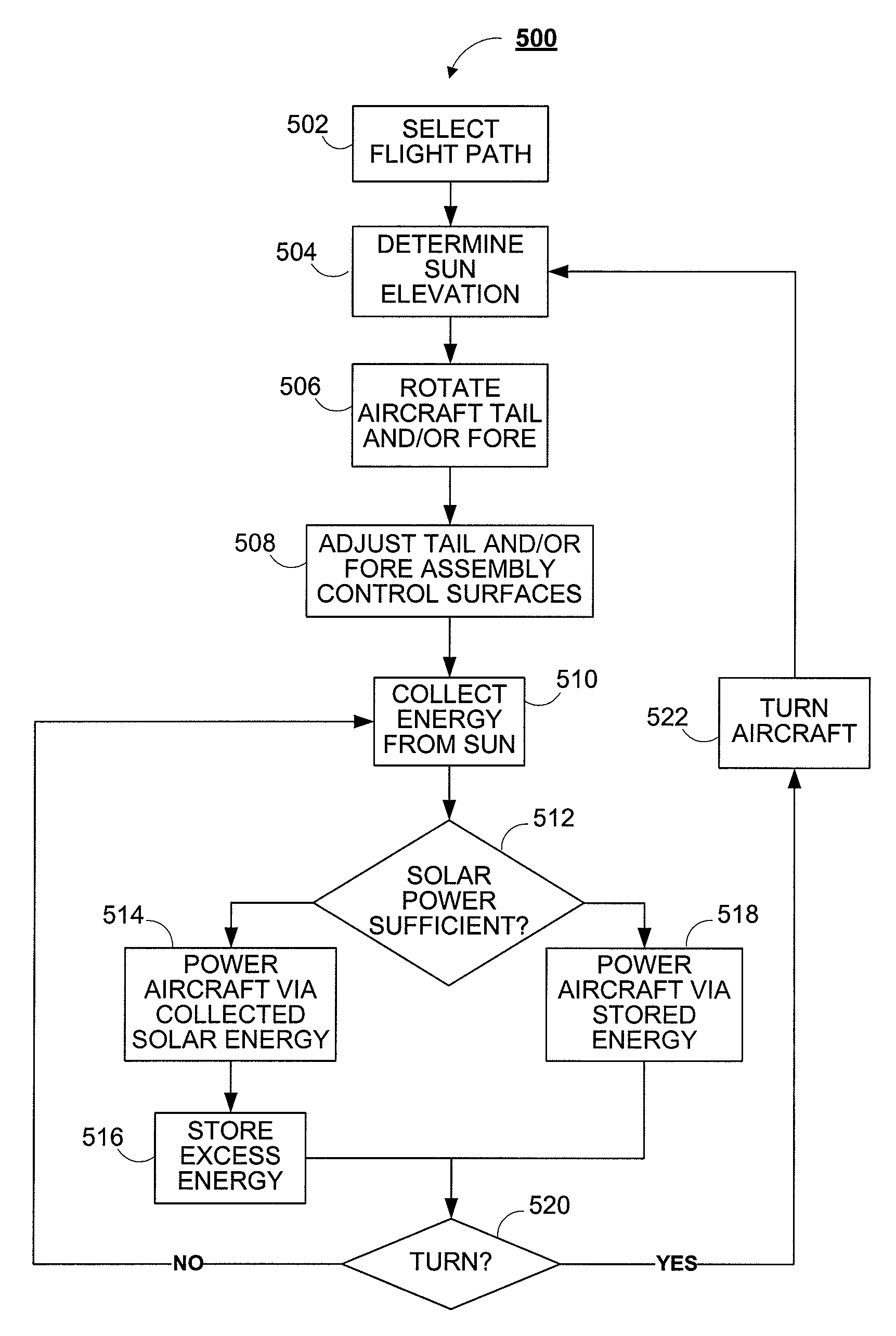
[0011]In another embodiment, the aircraft includes a fore assembly, which, like the tail assembly is rotatably coupled to the fuselage. The fore assembly includes at least two fins. Solar cells are mounted to the upper surfaces of the fins. A front drive motor rotates the tail assembly about the longitudinal axis of the aircraft to track the sun and thereby increase the fins' exposure to sunlight during flight. In such an embodiment, the flight controller controls the front drive motor and adjusts the flight control surfaces of the aircraft based on the rotational position of the front assembly.
[0012]According to another aspect, the invention relates to a method of powering an aircraft having solar cells mounted on the tail of the aircraft. The method includes determining an elevation of the sun relative to a current bearing of the aircraft. The aircraft rotates its tail assembly about a longitudinal axis of the aircraft based on the sun's elevation and a bearing of the aircraft. The rotation increases the exposure of the solar cells to the sun. In one embodiment, the method also includes rotating a fore assembly of the aircraft to increase exposure to the sun to solar cells mounted on the fore assembly. The method includes powering the aircraft using energy output by the solar cells. The control surfaces of the aircraft are adjusted to maintain the bearing.

Problems solved by technology

As a result, during large portions of the day, particularly in the fall and winter, they suffer from reduced sun exposure, or exposure to the sun at angles that are non-optimal for solar-cell power generation.
Such solar arrays substantially add to the weight of the aircraft, requiring more powerful motors and larger flight surfaces.

Method used


Image

  • Solar-powered aircraft with rotating flight surfaces
  • Solar-powered aircraft with rotating flight surfaces
  • Solar-powered aircraft with rotating flight surfaces

Examples


Embodiment Construction

[0024]To provide an overall understanding of the invention, certain illustrative embodiments will now be described, including solar-powered aircraft and methods for their operation. However, it will be understood by one of ordinary skill in the art that the systems and methods described herein may be adapted and modified as is appropriate for the application being addressed and that the systems and methods described herein may be employed in other suitable applications, and that such other additions and modifications will not depart from the scope hereof.

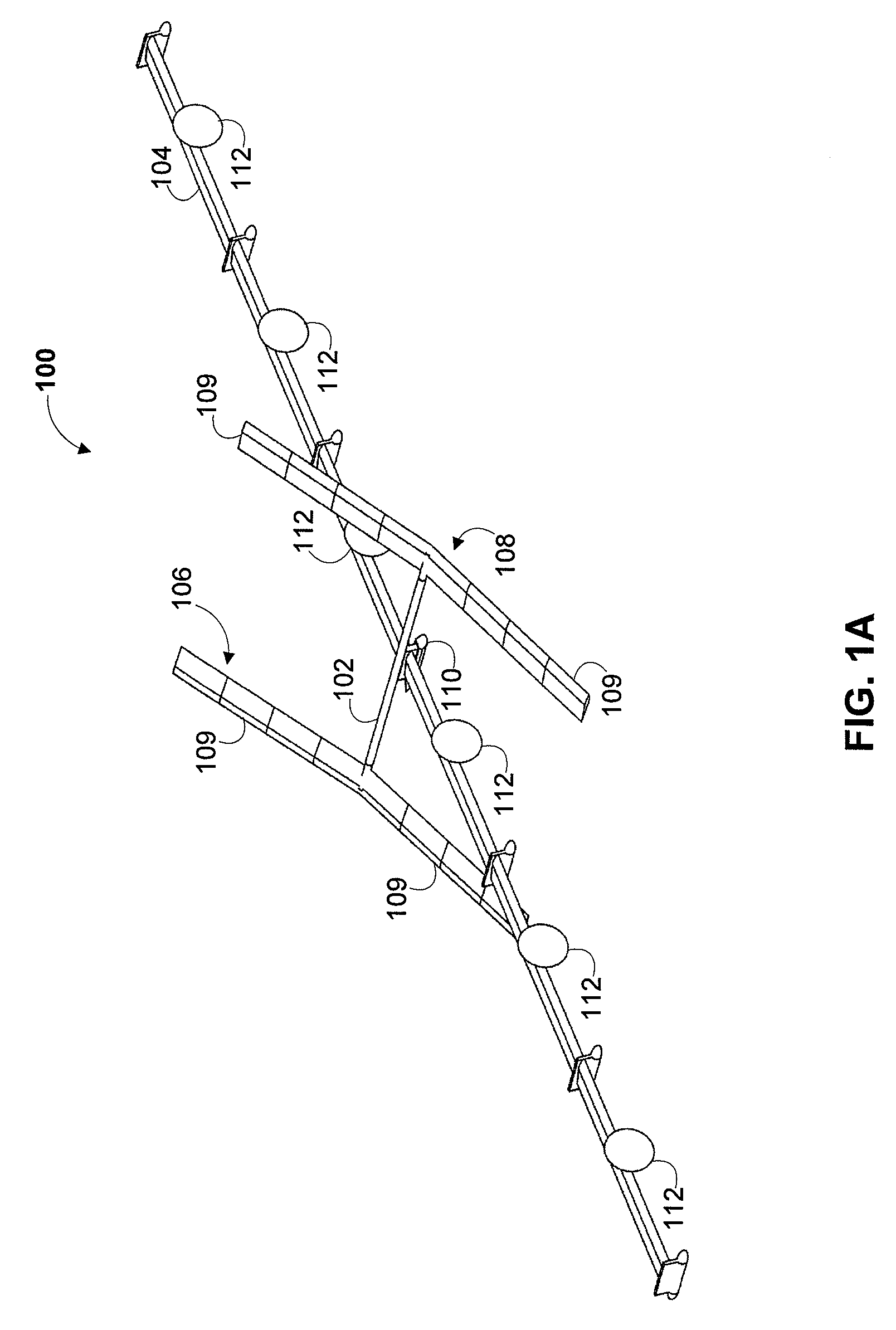
[0025]FIG. 1A is a schematic diagram of solar-powered aircraft 100, according to an illustrative embodiment of the invention. The solar-powered aircraft includes a fuselage 102, a set of wings 104, a tail assembly 106, and a fore assembly 108, and a payload compartment 110. The solar-powered aircraft is propelled by a series of electric motors 112 mounted on the wings 104.

[0026]The fuselage 102 is formed from a light weight material...


PUM


Abstract

A solar-powered aircraft having a rotating tail assembly and / or a fore assembly is provided. The tail and fore assemblies have solar cells mounted on their upper surfaces and are rotated during flight to track the sun.

Description

CROSS-REFERENCE TO RELATED APPLICATIONS[0001]This claims the benefit of U.S. Provisional Application No. 61 / 128,510 filed May 22, 2008, entitled, “Aerial Vehicle with Sun Tracking Tail,” and U.S. Provisional Application No. 61 / 130,148 filed May 27, 2008, entitled, “Aerial Vehicle with Sun Tracking Tail,” the entirety of each of which is incorporated herein by reference.FIELD OF THE INVENTION[0002]The invention relates to solar-powered aircraft. More particularly, the invention relates to solar-powered aircraft having solar arrays that track the sun.BACKGROUND OF THE INVENTION[0003]Several efforts have been made in the past to develop solar-powered aircraft, including, for example, the HELIOS solar-powered aircraft developed by NASA. Such solar-powered aircraft typically generate power from solar cells affixed to the upper surfaces of the wings and tail. However, in these aircraft, the wings and tail are fixed in position. As a result, during large portions of the day, particularly i...

Claims


Application Information

Patent Timeline
IPC IPC(8): B64D27/24G05D1/00H01M8/02H01M8/18
CPCB64C27/26B64C2201/028B64C2201/042B64C2201/108Y02T50/69B64D27/24B64D2211/00H01M8/18Y02T50/62B64C2201/165Y02E60/50Y02T50/50Y02T50/60B64U10/25B64U50/19B64U50/13B64U30/295B64U50/31B64D27/353B64U30/20
Inventor MINELLI, ROBERT J.HAASE, STEPHENKUTYN, RICHARD
Owner ORBITAL SCIENCES CORPORATION
Learn More