Earth Stress Management and Control Process For Hydrocarbon Recovery

a technology of earth stress and hydrocarbon recovery, applied in seismology for waterlogging, borehole/well accessories, instruments, etc., can solve the problems of over-pore pressure, large enough to exceed the mechanical limits of penetrating wells, and negatively affect the mechanical integrity of wells

Inactive Publication Date: 2009-11-26
SEARLES KEVIN H +4
View PDF42 Cites 11 Cited by
  • Summary
  • Abstract
  • Description
  • Claims
  • Application Information

AI Technical Summary

Problems solved by technology

The pressure or temperature changes, induced during the injection and / or withdrawal of pressurized fluids, result in stresses to the formation that may lead to some combination of fracturing, expansion and contraction of the subterranean formations.
These fracturing, expansion and contraction processes typically cause excess pore pressure and stress changes within the formations that may be large enough to negatively impact well mechanical integrity, productivity, injectivity and conformance.
They may also be large enough to exceed the mechanical limits of penetrating wells.
If the mechanical limits are exceeded, some combination of expansion and fracturing of the well or subterranean formation may occur.
As a result, the penetrating wells may no longer be capable of sustaining reliable hydrocarbon production safely and without risk to the environment.
For water flooding, the expansion and fracturing process may lead to “short circuiting” of injector-producer patterns and loss of pressure support.
For water disposal, these processes may lead to a loss of containment that may result in repressurization of untargeted zones and, potentially, regulatory and environmental consequences.
These conventional approaches fall short of being generalized to account for multiple subterranean layers and variable, time-dependent well performance.
In addition, even though displacement measurements from field surveillance may indicate the presence of multi-well interactions, conventional approaches do not scale very easily to account for these interactions at the field-level.
Moreover, the scope of the prior art has been limited to detecting some time-dependent, single-well characteristic of the resident or injected fluids, changes in the geometry of a hydrofracture, or a principal stress change within the very near-well regime for predicting phenomena, such as the potential for or onset of sand production.

Method used


Image

  • Earth Stress Management and Control Process For Hydrocarbon Recovery
  • Earth Stress Management and Control Process For Hydrocarbon Recovery
  • Earth Stress Management and Control Process For Hydrocarbon Recovery

Examples


Embodiment Construction

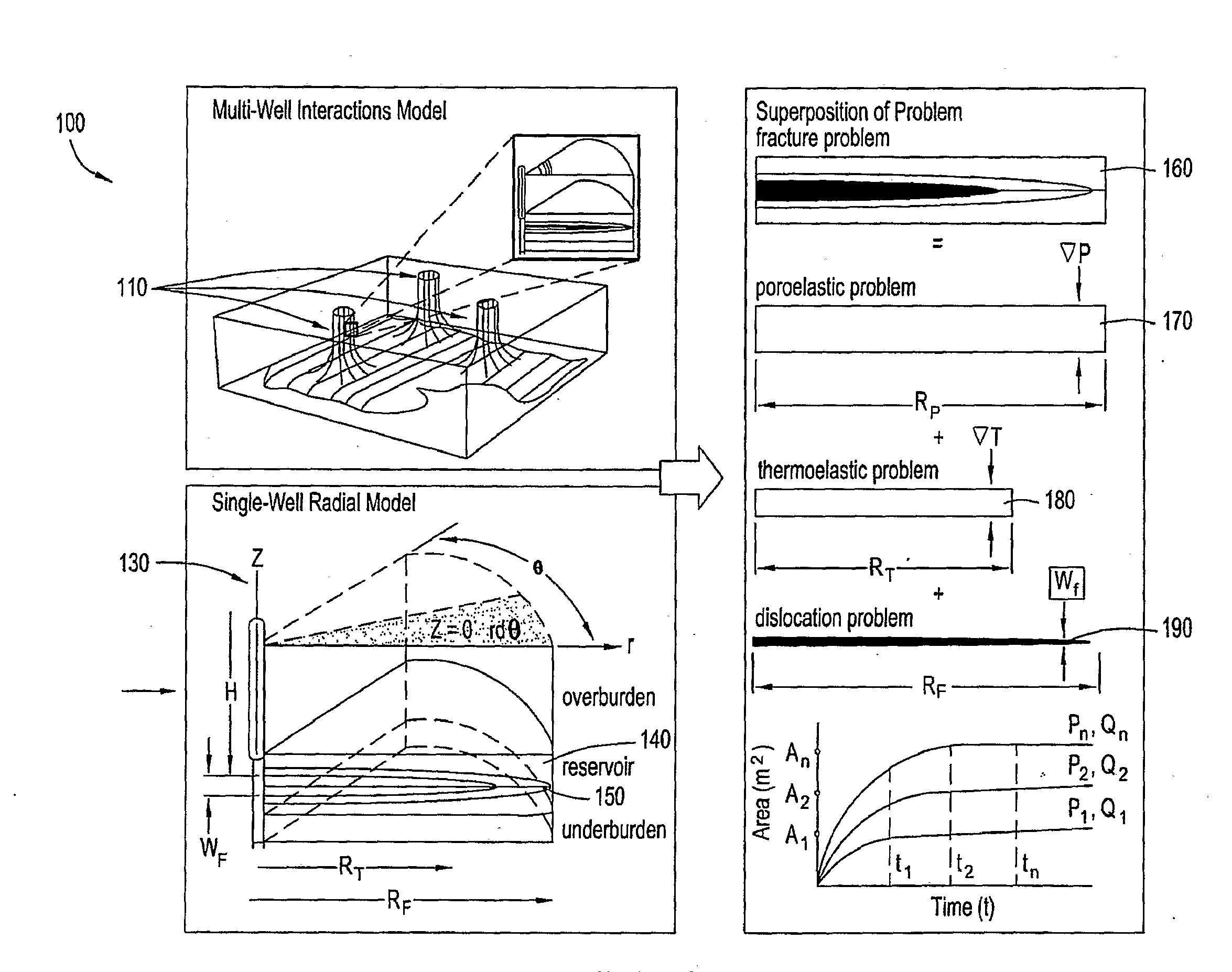
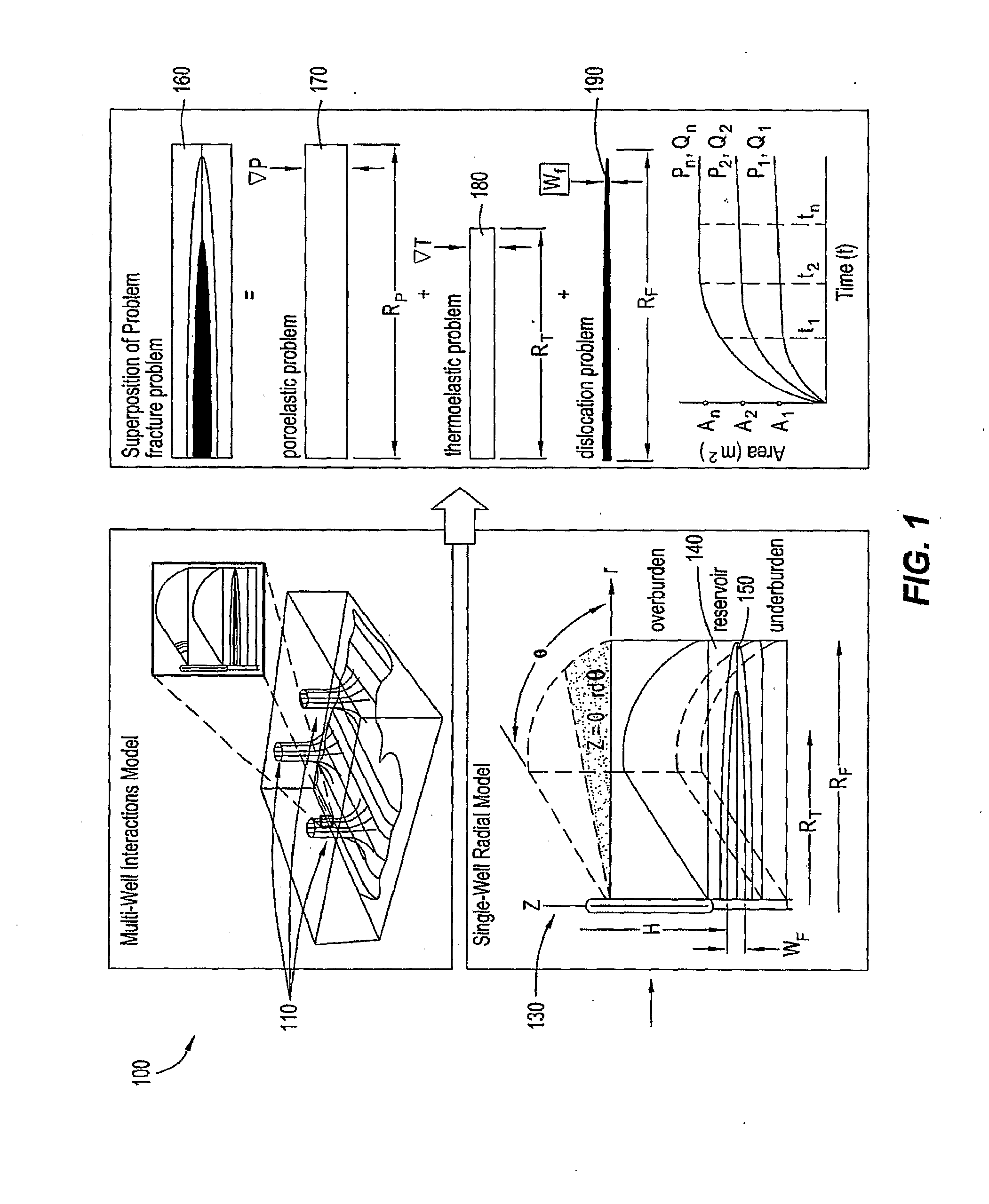
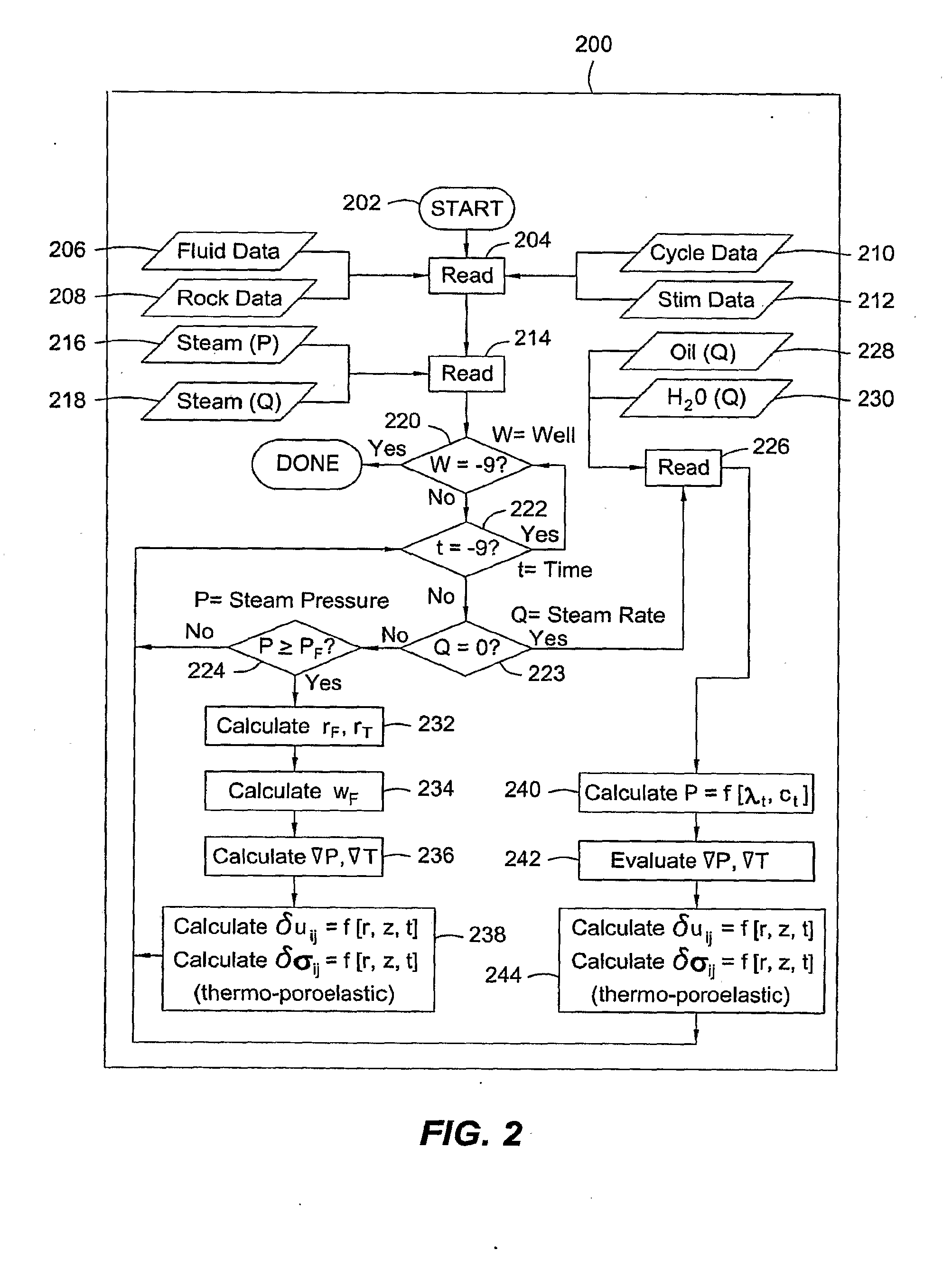
[0039]Embodiments of the present invention provide a systematic, transient analysis method for determining the formation effective displacement, stress and excess pore pressure field quantities at any depth within a stratified subterranean formation resulting from the subsurface injection and / or withdrawal of pressurized fluids; a process for controlling recovery to improve well interactions while preventing excessive strain or stress-induced well deformations and mechanical failures; and a process for controlling fluid injection parameters to improve well interactions and control hydrofracture geometries.

[0040]Embodiments of the present invention also incorporate data from field surveillance, well logs, well trajectories, completions and / or various other injection or production sources for controlling various well parameters, and in self-calibrating the model. Water flood and / or water disposal operations may also be considered for some embodiments in creating or evaluating a fieldw...


PUM


Abstract

A method for controlling hydrocarbon recovery to improve well interactions while preventing excessive strain or stress-induced well deformations and mechanical failures is described. The method incorporates a systematic, transient analysis process for determining the formation effective displacement, stress and excess pore pressure field quantities at any depth within a stratified subterranean formation resulting from the subsurface injection and / or withdrawal of pressurized fluids.

Description

CROSS-REFERENCE TO RELATED APPLICATIONS[0001]This application claims the benefit of U.S. Provisional Application No. 60 / 845,951, filed 20 Sep. 2006.[0002]U.S. provisional patent application, attorney docket number 2006EM115, entitled “Fluid Injection Management Method for Hydrocarbon Recovery,” and U.S. provisional patent application, attorney docket number 2006EM117, entitled “Earth Stress Analysis Method for Hydrocarbon Recovery,” filed concurrently herewith, contain subject matter related to that disclosed herein, and are incorporated herein by reference in their entirety.BACKGROUND OF THE INVENTION[0003]1. Field of the Invention[0004]Embodiments of the present invention relate generally to the analysis of earth stresses associated with hydrocarbon recovery and, more particularly, to determining effective displacements and stresses resulting from the injection and / or withdrawal of pressurized fluids.[0005]2. Description of the Related Art[0006]Hydrocarbon recovery processes may o...

Claims


Application Information

Patent Timeline
Patent Type & Authority Applications(United States)
IPC IPC(8): G06F19/00G01V1/40
CPCE21B49/006E21B43/00
Inventor SEARLES, KEVIN H.LONG, TED A.PAKAL, RAHULDALE, BRUCE A.BAILEY, JEFFREY R.
Owner SEARLES KEVIN H
Why Eureka
Try Eureka