Robot arm

a robot arm and arm body technology, applied in the field of robot arms, can solve the problems of affecting the production yield of glass substrates, the rough outer surface of the supporting rods, and the impact of glass substrates, so as to reduce the possibility of scraping workpieces held thereon, and reduce the accumulation of dust thereon

Inactive Publication Date: 2009-12-03
ADVANCED INT MULTITECH CO LTD
View PDF7 Cites 12 Cited by
  • Summary
  • Abstract
  • Description
  • Claims
  • Application Information

AI Technical Summary

Benefits of technology

[0008]Therefore, the object of the present invention is to provide a robot arm that can alleviate accumulation of dust thereon, and that can lower the possibility of scraping workpieces held thereon.

Problems solved by technology

However, since the resin-impregnated carbon prepreg has relatively large pores, resin in the resin-impregnated carbon prepreg is likely to leak via the pores during the hot-pressing process, thereby resulting in a rough outer surface of the supporting rods 132.
Moreover, the dust accumulated in the dents and holes of the supporting rods 132 may scrape the glass substrates 100 held on the supporting rods 132, thereby affecting adversely the production yield of the glass substrates 100.

Method used


Image

  • Robot arm
  • Robot arm
  • Robot arm

Examples


Embodiment Construction

[0018]Before the present invention is described in greater detail, it should be noted that like elements are denoted by the same reference numerals throughout the disclosure.

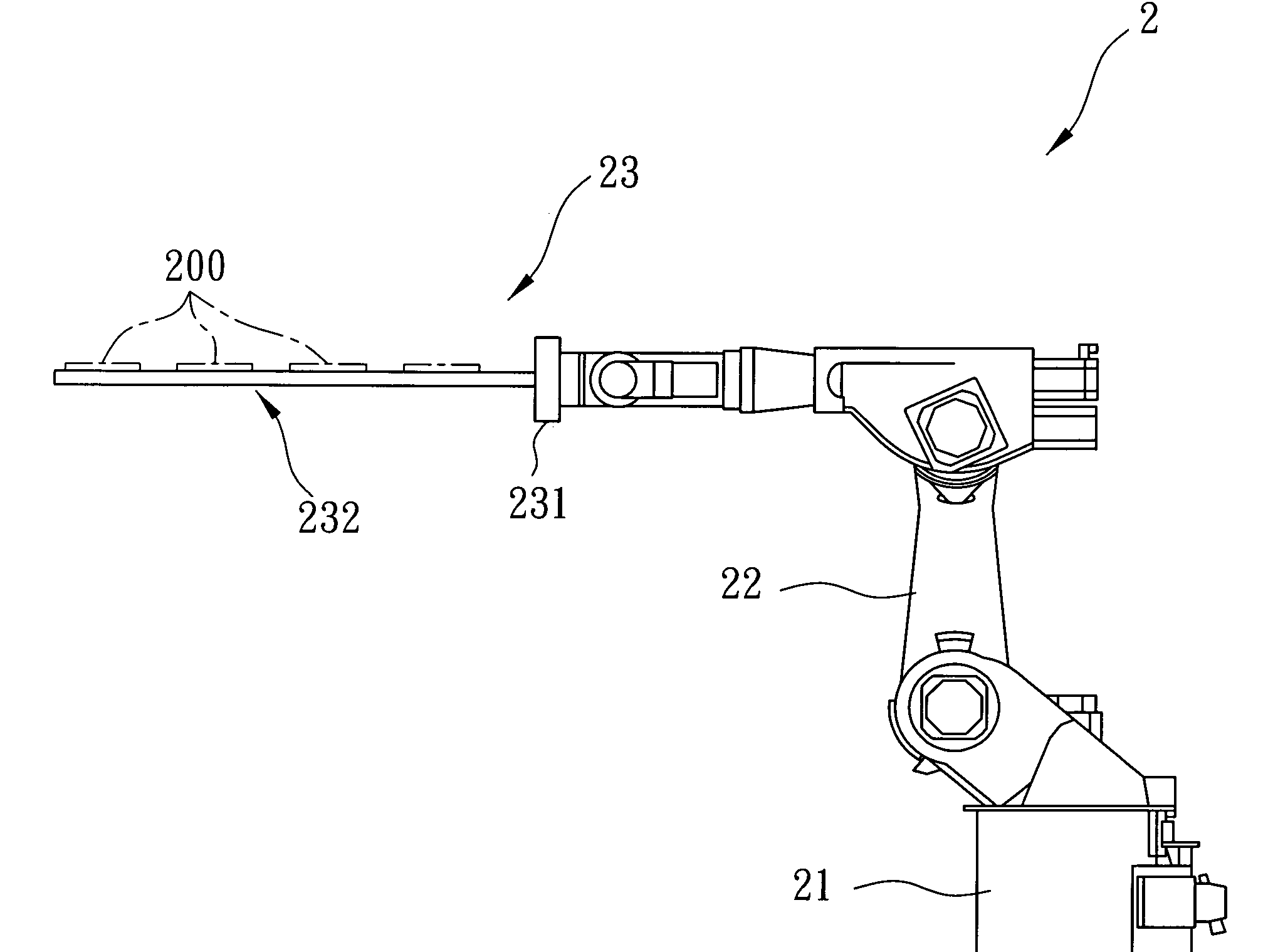
[0019]As shown in FIG. 4, the first preferred embodiment of a robot arm 2 according to the present invention is adapted for supporting workpieces 200 thereon. The robot arm 2 comprises a driving device 21, a working arm member 22, and a workpiece placement unit 23.

[0020]As further shown in FIGS. 5 and 6, the workpiece placement unit 23 includes a base seat 231 coupled to the working arm member 22, and a plurality of parallel and spaced-apart hollow supporting rods 232. Each of the supporting rods 232 extends from the base seat 231, is adapted for supporting a plurality of the workpieces 200 thereon, and defines a passage 24 therethrough. In this embodiment, each of the supporting rods 232 is made of a composite material including a hollow rod structure 233 that has a plurality of fibrous layers 239 made of resin...


PUM

PropertyMeasurementUnit
structureaaaaaaaaaa

Abstract

A robot arm includes a working arm member, a workpiece placement unit, and a driving device. The workpiece placement unit includes a base seat coupled to the working arm member, and a hollow supporting rod with a suction unit. The supporting rod extends from the base seat, is adapted for supporting a workpiece thereon, and defines a passage therethrough. The supporting rod is made of a composite material including a hollow rod structure having at least one fibrous layer that is made of resin-impregnated carbon prepreg, and an outer covering layer made of fiberglass material and covering an outer surface of the hollow rod structure. The driving device is coupled to the working arm member, is operable to drive the working arm member for moving the workpiece placement unit, and is further operable for extracting air from the passage so that the workpiece supported by the supporting rod is held in position by the suction unit.

Description

CROSS-REFERENCE TO RELATED APPLICATION[0001]This application claims priorities of Taiwanese Application No. 097119663, filed on May 28, 2008, and Taiwanese Application No. 097209323, filed on May 28, 2008.BACKGROUND OF THE INVENTION[0002]1. Field of the Invention[0003]The invention relates to a robot arm, more particularly to a robot arm adapted for supporting a workpiece thereon.[0004]2. Description of the Related Art[0005]As shown in FIG. 1, a conventional robot arm 1 is adapted for supporting glass substrates 100 thereon, and includes a working arm member 12, a supporting unit 13 coupled to the working arm member 12, and a driving device 11 for driving the working arm member 12 to move the supporting unit 13.[0006]As further shown in FIGS. 2 and 3, the supporting unit 13 includes a base seat 131 coupled to the working arm member 12, and a plurality of parallel and spaced-apart hollow supporting rods 132 extending from the base seat 131. Each of the supporting rods 132 includes a ...

Claims


Application Information

Patent Timeline
Patent Type & Authority Applications(United States)
IPC IPC(8): B25J18/00B25J9/00B32B1/08B32B5/02
CPCB25J9/0012B25J15/0616Y10T428/1393Y10T74/20305B32B5/28B32B5/26B32B2260/021B32B2260/048B32B2262/101B32B2262/106
Inventor CHANG, EHR-CHOUHE, JIA-CHI
Owner ADVANCED INT MULTITECH CO LTD
Why Eureka
Try Eureka