[0012]It is desirable that the collected material is prevented from entering the blower vac, as obstruction of its internal
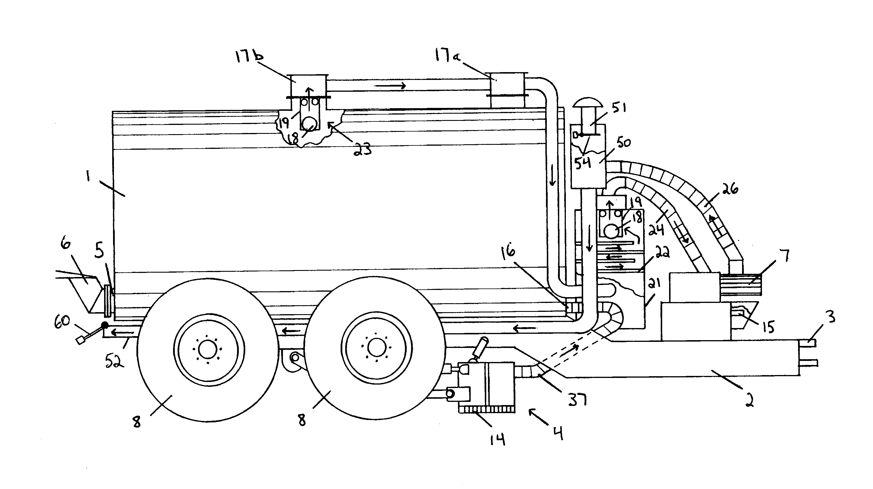
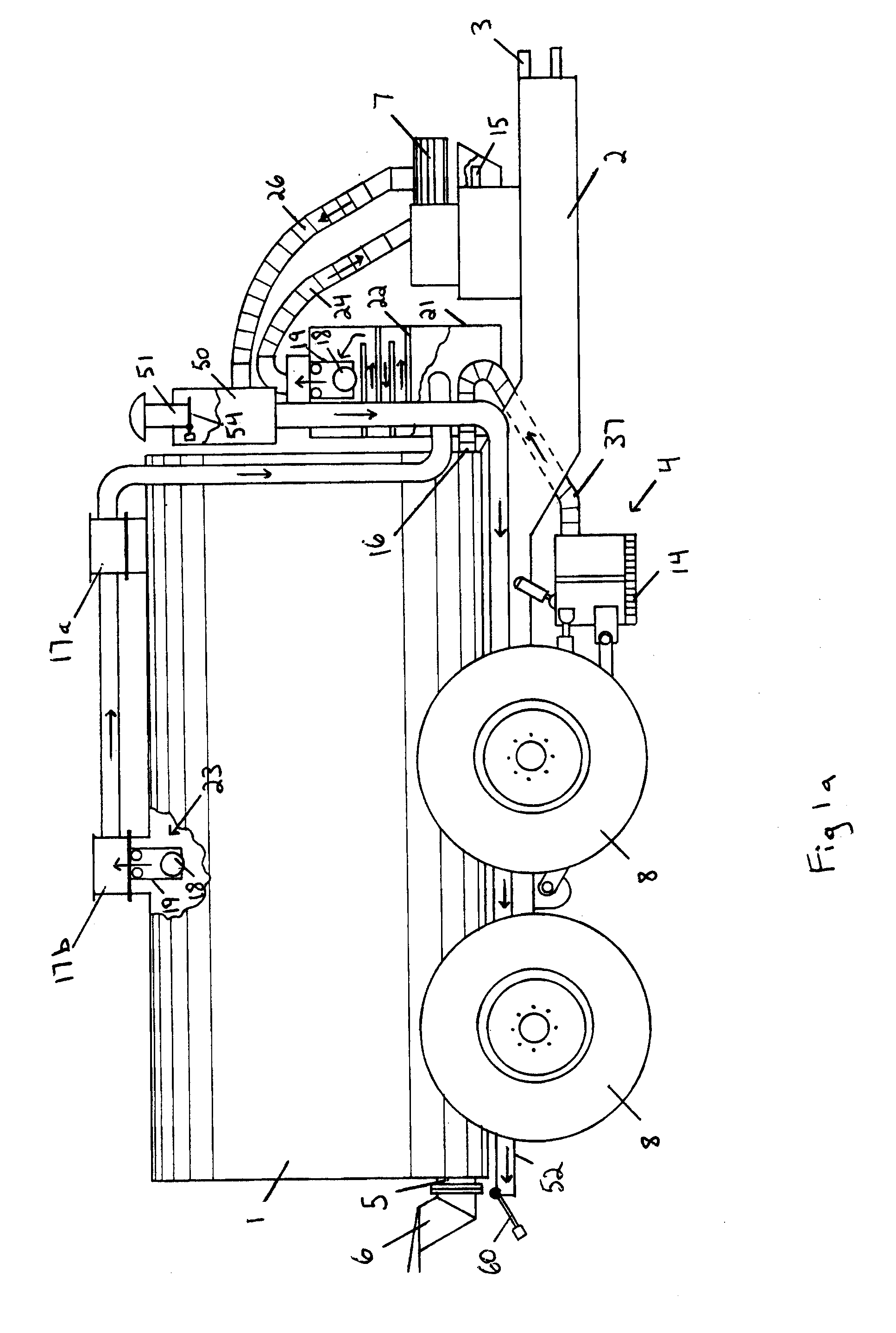
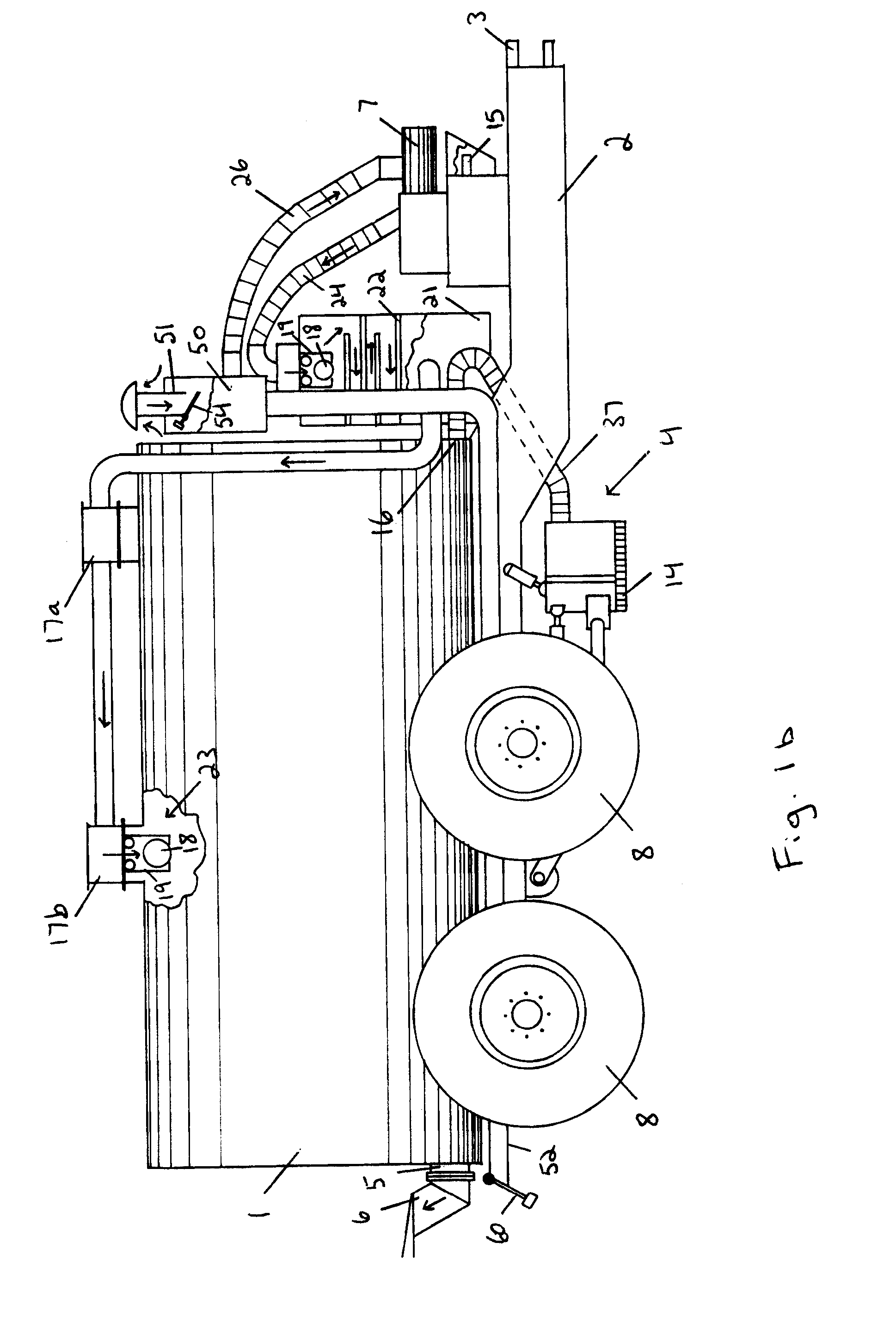
moving parts can cause significant damage to the blower vac. The vacuum tank includes a vacuum outlet that may comprise two or more vacuum outlets spaced apart along the top of the tank. By using two or more vacuum outlets, the velocity through each outlet is decreased, thereby reducing the likelihood that the collected material can become entrained in the air flowing through the outlets. The outlets may be of the same size or different sizes in order to preferentially direct the collected material to different parts of the tank. Each outlet may include a primary trap to further reduce the likelihood of material escaping through the vacuum outlet, particularly when the tank is full. Any suitable primary trap design may be used and the primary trap is preferably readily cleaned by reducing the air flow through the vacuum outlet.
[0013]Air flowing from the vacuum outlet may be directed to a secondary trap for yet further reducing the likelihood that entrained debris will enter the blower vac. The secondary trap may be of any suitable design and may comprise a chamber containing a series of baffle plates that are arranged to create a serpentine path. Alternatively, the chamber may contain a plurality of perforated impingement plates stacked with the perforations in an offset relationship. The secondary trap may be similar to a knock-out pot in that it may be designed for the removal of liquid from the air flow, particularly liquid droplets. The secondary trap may be cleaned by reversing the direction of air flow through the trap and may be additionally or alternatively cleaned using a supplemental
stream of air or water to flush out the contents of the trap. The secondary trap may include a drain and the drain may be directed back into the vacuum tank. The outlet of the secondary trap is preferably free of collected material or droplets and is provided to the blower vac.
[0015]The valve means may be used as part of any liquid or semi-liquid material
collection system that both draws and expels material pneumatically. The valve means may be automatically adjustable or manually adjustable. The valve means may comprise a three-way valve mechanism that permits selection of a single flow path from two different flow paths, for example and L-ported
ball valve that may be alternated between two flow paths. The valve means may comprise a pair of check valves, one
check valve in each of the intake and exhaust flow paths. The check valves may be oppositely oriented to permit air to flow into the valve means through only one flow path (the intake flow path) and out of the valve means by only the other flow path (the exhaust flow path). In this manner, the valve means is automatically adjustable in response to a change in the direction of flow through the blower vac. The valve means may include a valve chamber and the check valves need not necessarily both be located in the valve chamber. The valve means is particularly advantageous in allowing an air intake and exhaust of the
system to be separated, thereby permitting the intake to be elevated with respect to the material being collected and the exhaust to be located distantly from the operator. The elevated exhaust reduces the likelihood of debris entering the blower vac when blowing air into the tank and the distant exhaust improves operator health and safety.
[0017]The suction inlet may be height adjustable independently of any height adjustment of the collection means in response to the quantity of material being collected; this permits a scraping element of the collection means to remain in contact with the floor surface while allowing the suction inlet to be adjusted relative in height thereto in response to a large quantity of material being collected. Any suitable mechanism may be employed to adjust the height of the suction inlet. The suction inlet is preferably connected to the vacuum inlet by a flexible connection in order to facilitate the height adjustment. By setting the suction inlet closer to the floor surface that the material is being collected from more material may be collected, thereby leaving less material in the collection means at the end of a pass through an
alley. However, if set close to the floor, the suction inlet will have more material to pick-up and driving speed may have to be reduced. There is therefore an optimal trade-off between speed and completeness of collection. A snorkel may be provided alongside the suction inlet for introducing a small quantity of air into the material as it is being collected. This small quantity of air is entrained with the material and makes it easier to lift from the floor and easier to pneumatically convey, particularly for materials with a thick consistency. The snorkel may include a small valve to set the quantity of air provided to the suction inlet according to the consistency of the material being collected.
[0018]The collection means may include a variable width mechanism. The variable width mechanism is particularly useful in the collection of manure from alleys or gutters, as it allows the collection means to fit the width of the alley or gutter and reduces the likelihood of manure escaping around the sides of the collection means. The collection means may include wings that are pivotally attached to each side of the collection means and able to pivot about a vertical pivot axis. The wings may be biased outwardly towards or against the sidewalls of the alley or gutter and may resiliently adapt to changes in the width of the gutter by pivoting about the vertical pivot axis. The wings may move about the vertical pivot axis in response to a change in the distance between the side-wall of the alley and the collection means. The wings may be biased by a spring means or a suitable fluid cylinder arrangement, such as a pneumatic or
hydraulic fluid displacement cylinder, a captive gas
shock absorber, or a combination thereof. The wings may automatically adjust to the width of the alley or gutter or may be manually adjusted by an operator of the apparatus. The adjustment may be conducted using controls within the
towing vehicle. The wings may include skid plates or wear strips to reduce the likelihood of damaging the wings due to operator driving error.
[0019]The
discharge outlet is provided at the rear of the vacuum tank. The
discharge outlet may be connected to any manure
distribution system suitable for liquid or semi-
liquid manure, such as a spreader plate or sub-surface injection
system. Alternatively, the
discharge outlet may be connected via a fluid conduit for transferring the manure to a separate spreading apparatus or a holding vessel. The vacuum inlet is provided at the front of the tank, preferably in a
lower half thereof below the horizontal midline of the tank. Filling the tank from the front and discharging the tank through the rear causes a flushing of the collected materials through the tank. This causes substantially all of the material in the tank to be discharged and mitigates material build-up in the front of the tank. During collection, a remotely operable valve on the discharge outlet is closed to prevent inadvertent leakage from occurring. During tank discharge, a remotely operable valve on the vacuum inlet is closed to prevent material from being discharged through the collection means.

