Backup safety flow control system for concentric drill string

a safety flow control and drill string technology, applied in the direction of drilling pipes, drilling/well accessories, sealing/packing, etc., can solve the problems of reducing the ability to retrieve fluids later, and affecting the safety of the operation

Inactive Publication Date: 2009-12-03
VETCO GRAY
View PDF32 Cites 19 Cited by
  • Summary
  • Abstract
  • Description
  • Claims
  • Application Information

AI Technical Summary

Benefits of technology

[0007]A technique is presented for providing a double-barrier to formation fluids in a concentric drill string having an inner bore and an annulus. The technique prevents formation fluids from flowing uncontrollably upward through the concentric drill string to the surface. The first barrier to formation fluids is a primary flow control system that is provided to prevent formation fluids from flowing to the surface during a well excursion. The primary flow control system comprises a primary inner bore shutoff valve and a primary annulus shutoff valve. The primary inner bore shutoff valve may be used to block fluid flow through the inner bore of the concentric drill string. The primary annulus shutoff valve may be used to block fluid flow through the annulus of the concentric drill string.

Problems solved by technology

However, drilling mud can damage the formation around the wellbore, thereby reducing the ability to retrieve fluids later when the well is put into production.
If liquid drilling mud is used, the coal beds may be damaged by the encroaching drilling mud from the wellbore.
Because a column of air does not have the hydrostatic pressure of heavy drilling mud, valve assemblies have been developed to control the flow of fluid within the inner drill string and in the annulus between the inner and outer drill strings in the event that formation fluid begins to flow into the drill string, such as during a blowout or “kick.” However, problems have been experienced with these valve assemblies.
For example, these drill string valve assemblies have been known to leak.

Method used


Image

  • Backup safety flow control system for concentric drill string
  • Backup safety flow control system for concentric drill string
  • Backup safety flow control system for concentric drill string

Examples


Embodiment Construction

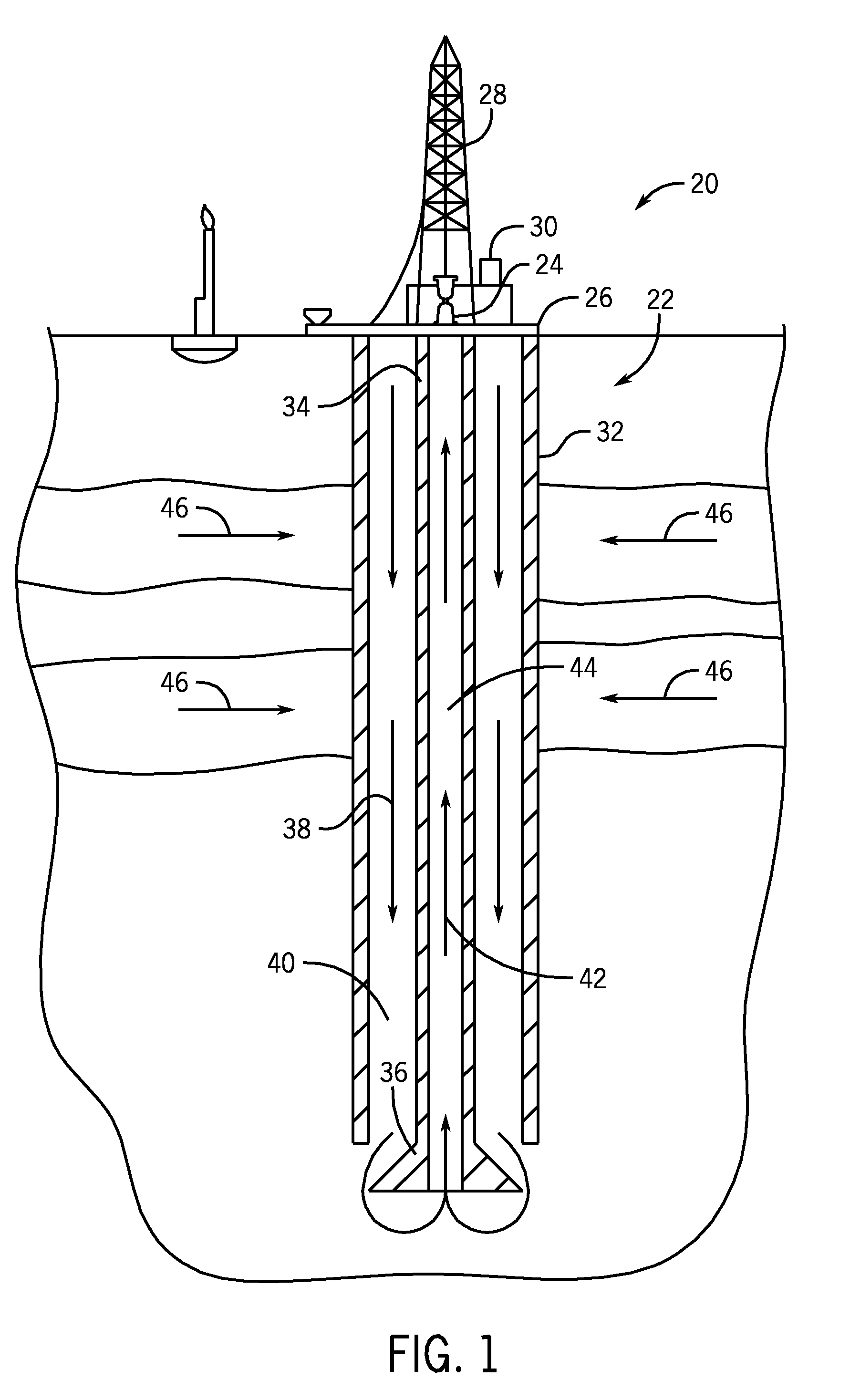
[0020]Referring now to FIG. 1, the present invention will be described as it might be applied in conjunction with an exemplary technique, in this case a drilling system for drilling wells, as represented generally by reference numeral 20. In the illustrated embodiment, the drilling system 20 comprises a concentric drill string 22. The drill string 22 is rotated by a rotary table 24 supported by a drilling platform 26. The drilling system 20 also comprises a derrick 28 to support the drill string 22 and its components during assembly and disassembly of the drill string 22. The illustrated system 20 also comprises a drilling fluid supply and recovery system 30. In this embodiment, the drilling fluid is a gas, such as air. However, other drilling fluids may be used.

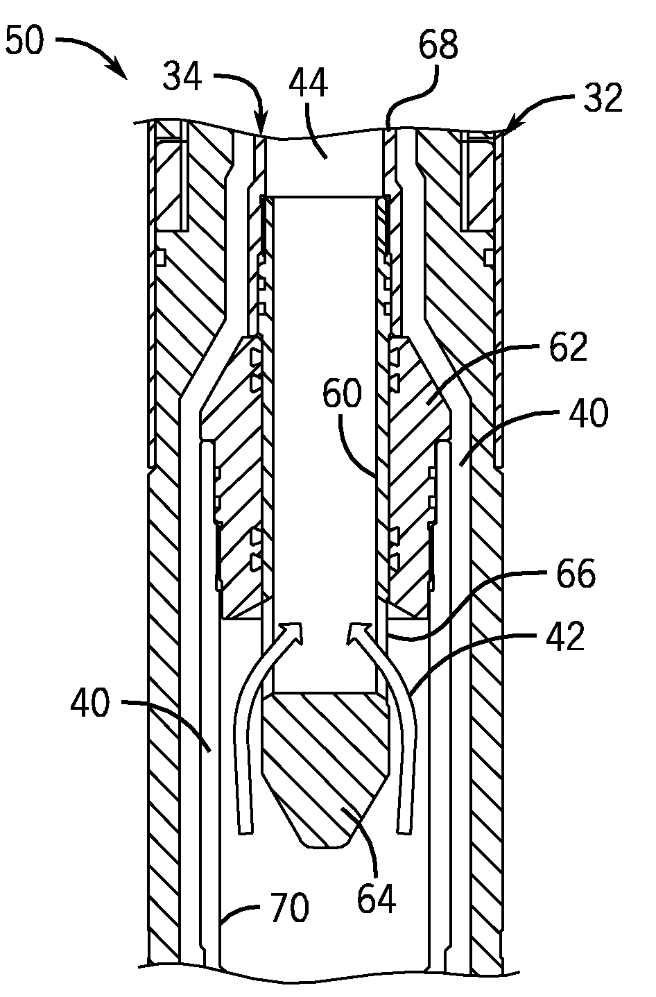
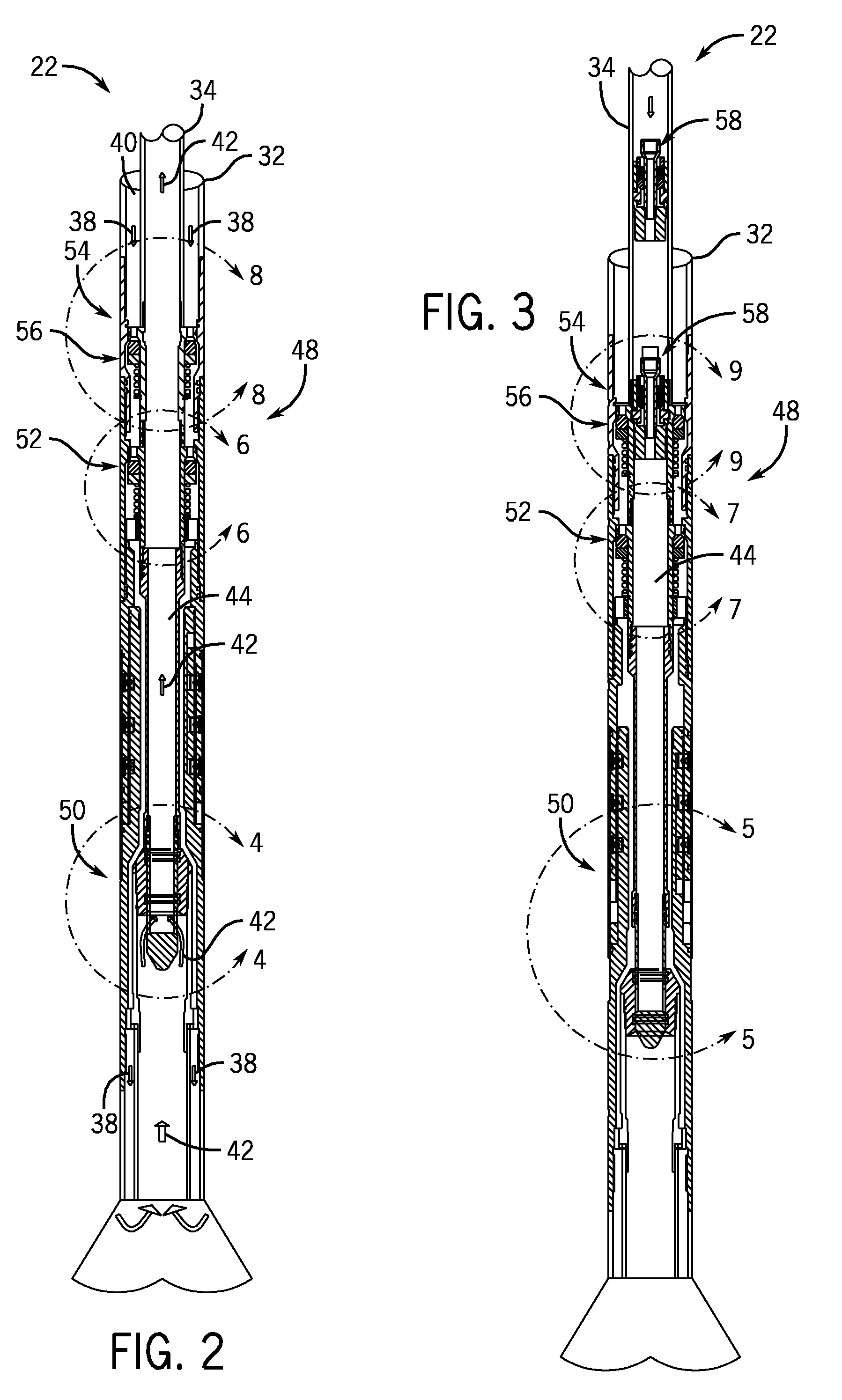
[0021]In the illustrated embodiment, the drill string 22 is a concentric drill string having an outer housing 32 secured to an inner drill string 34. The drill string 22 also comprises a drill bit 36. As the drill string 22 ...


PUM


Abstract

A technique is presented for providing a double-barrier to formation fluids during drilling operations with a concentric drill string having an inner bore and an annulus. A primary flow control system is used to provide a first barrier to formation fluids in the inner bore and annulus of the drill string. A backup flow control system is used to provide a second barrier to formation fluids. The backup flow control system comprises a backup inner bore shutoff valve and a backup annulus shutoff valve. The backup inner bore shutoff valve is dropped from the surface through the inner bore of the drill string. The backup inner bore shutoff valve has spring-biased tabs that are configured to extend outward to contact an inner surface profile of the inner bore of the drill string. The backup annulus shutoff valve may be provided with the profile to receive the spring-biased tabs from the backup inner bore shutoff valve. When the tabs of the backup inner bore shutoff valve are disposed opposite the profile, the tabs of the backup inner bore shutoff valve are extended outward into the profile by a spring assembly, securing the backup inner bore shutoff valve within the drill string.

Description

BACKGROUND[0001]The invention relates generally to shutoff valves for wells. In particular, the invention relates to a backup shutoff valve system for a concentric drill string and a method for installing and using the backup shutoff valves in a concentric drill string.[0002]Most oil and gas wells are drilled with a rotary drilling rig. Typically, the drilling rig uses a string of drill pipe with a drill bit on the end. The drill string is rotated by the rotary drilling rig to rotate the drill bit into the ground. A drilling fluid is used to maintain control of the wellbore fluids in the well, as well as to remove the cutting from the wellbore. The drilling fluid may be pumped down the interior passage of the drill pipe, so that it may exit the drill bit through nozzles in the drill bit. The drilling fluid and cuttings are returned to the surface in the annulus space surrounding the drill pipe in the wellbore.[0003]In many cases, the drilling fluid is a liquid known as drilling mud....

Claims


Application Information

Patent Timeline
Patent Type & Authority Applications(United States)
IPC IPC(8): E21B33/06
CPCE21B17/18E21B34/08E21B21/12
Inventor CHAN, KWONG O.HE, HENRY X.
Owner VETCO GRAY
Why Eureka
Try Eureka