Bill validator - dispenser with improved security

Active Publication Date: 2009-12-03
COIN ACCEPTORS
View PDF1 Cites 8 Cited by
  • Summary
  • Abstract
  • Description
  • Claims
  • Application Information

AI Technical Summary

Benefits of technology

[0009]It is, therefore, an object of the present invention to provide a bill receiving device capable of dividing bills into two kinds, and separately storing the divided bills and paying out at least one specific denomination using a very simple and compact construction.
[0011]It is a further object of this invention to provide very reliable method for extracting a bill for payout by extraction, and determination of extraction of the rearmost bill out from a bill stack using an upper edge retainer / deflector and a rubber cam roller operating in a first direction, and then in a second direction.
[0012]There is another object of this invention to provide a bill receiving device capable to better protect the content of the two stacker boxes.
[0013]It is a further object of this invention to provide an improved method of protecting the bills in the stackers against thieves even when the power to the unit is off.
[0014]It is a further object of this invention to provide a higher security for bills while maintaining high bill acceptability rates even in hard weather conditions when humidity or icing occurs in the inlet.

Problems solved by technology

Vandalism has long been a problem for vending machines equipped with a Bill Validator.
Similarly, thieves may pry open the top of the door to gain access to bills in a dollar bill Validator.

Method used


Image

  • Bill validator - dispenser with improved security
  • Bill validator - dispenser with improved security
  • Bill validator - dispenser with improved security

Examples


Embodiment Construction

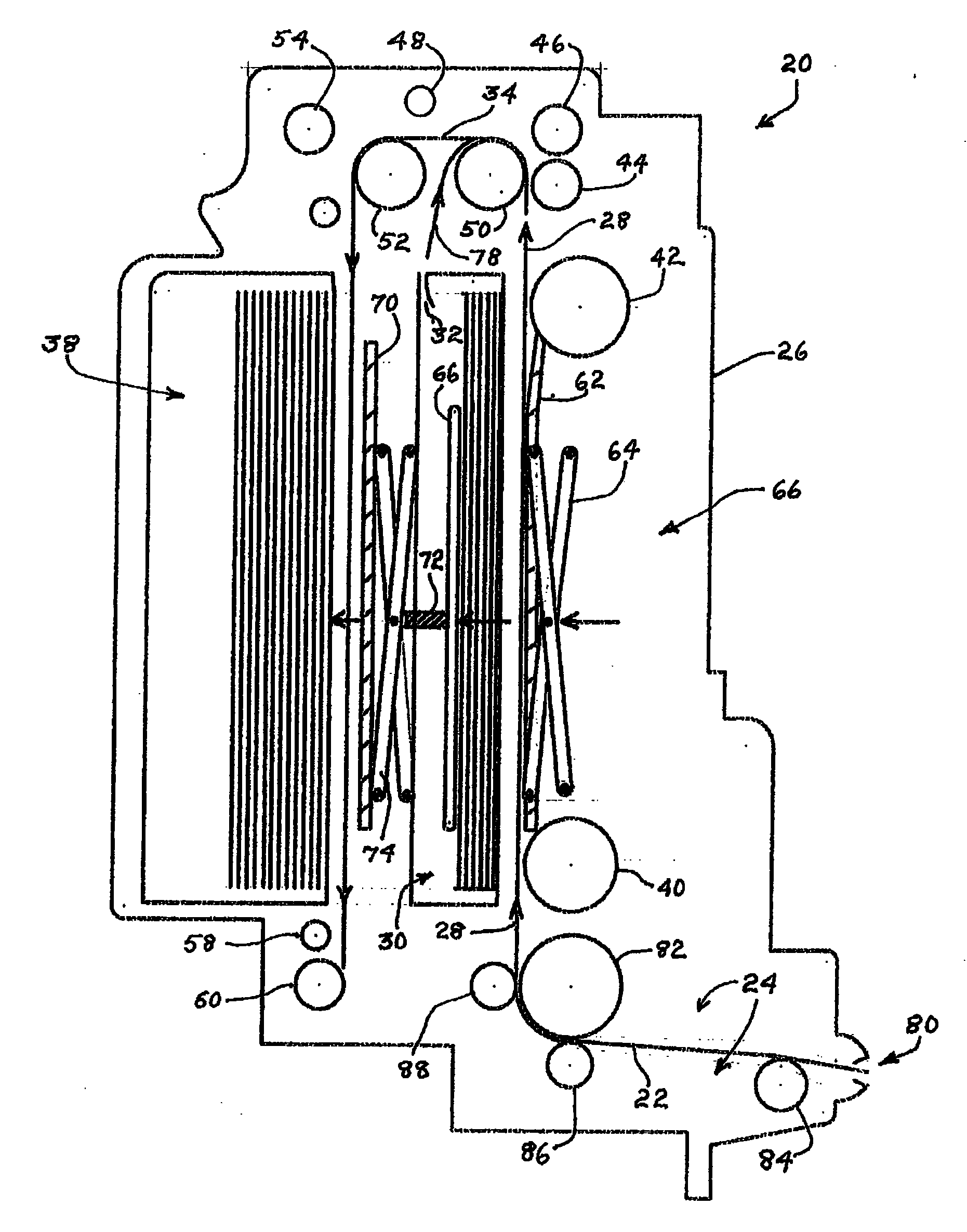
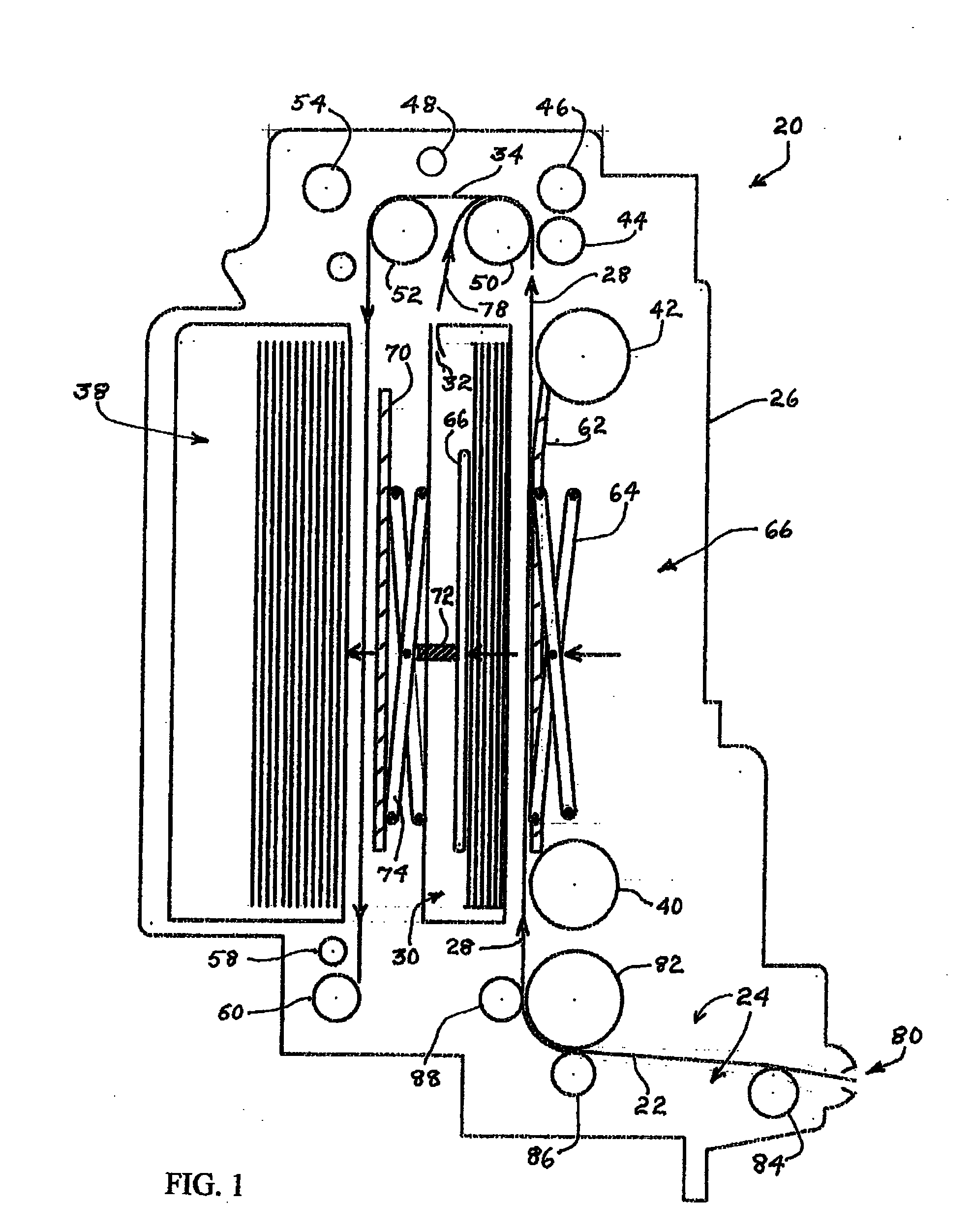
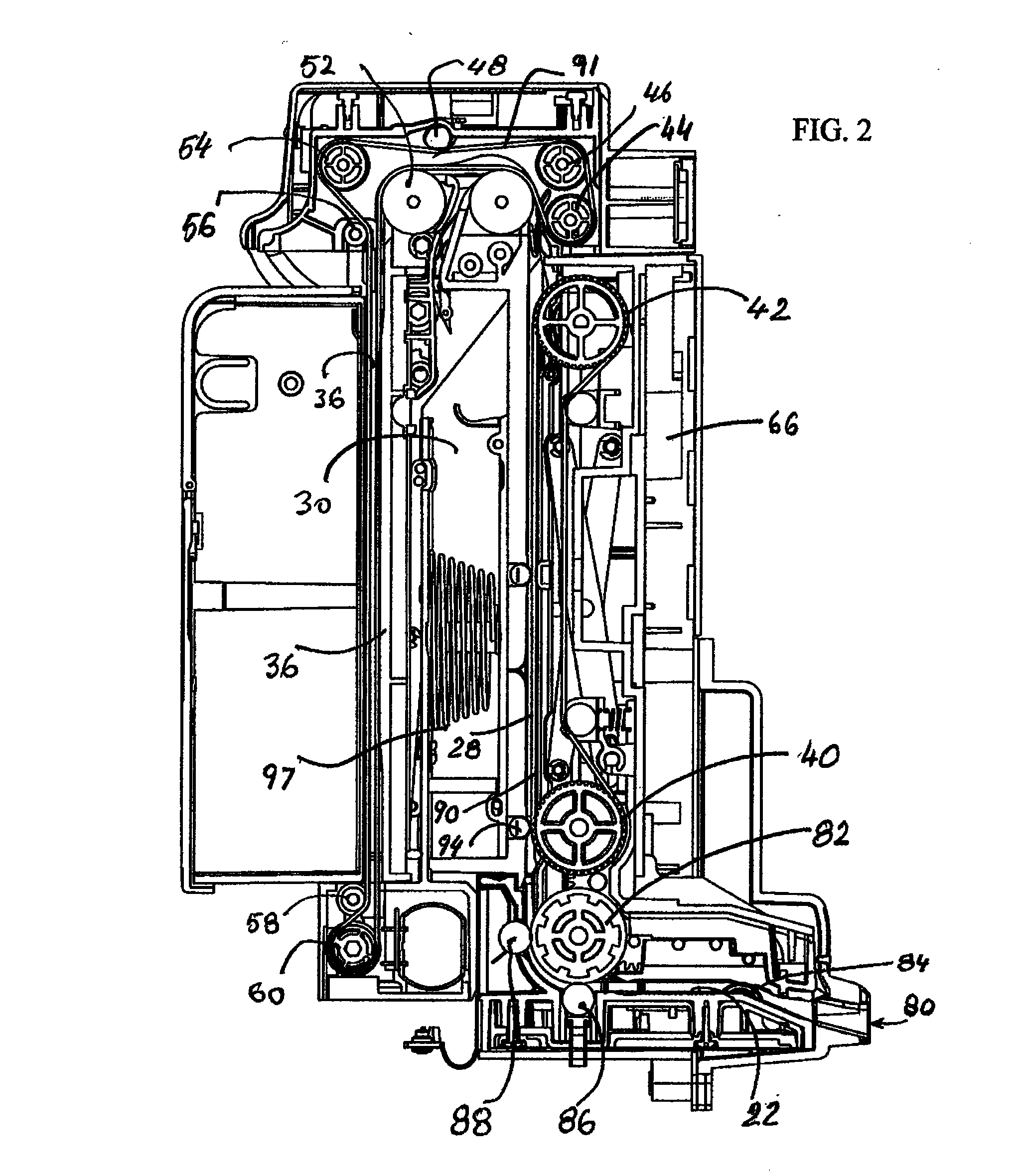
[0024]A simplified sectional side view drawing of the bill receiving and payout device 20 is shown in FIG. 1 having a bill validation passage 22 with its associated sensors and circuitry placed the general location 24 for the validation of inserted bills. Within the elongate portion 26 of the device 20, a validated bill is directed upward in a passage first direction 28 along the one side of a first bill receiving chamber 30 having a bill payback outlet 32. The passage first direction 28 is redirected around at path 34 and extends in the opposite passage second direction 36 along the rear side of the first bill receiving chamber 30. The second bill receiving chamber 38 extends along the outer side of the passage second direction 36 across from, and aligned with the first bill receiving chamber 30. The bill conveying apparatus for conveying a bill to the passage first or second directions 28 or 36 is accomplished by belts (not shown) moved along the passageways by pulleys 40 through ...


PUM


Abstract

A method is shown providing a Bill Validator that is adaptable for bill payback by utilizing an attachable bill hopper module to fit between the bill Stacker and the Bill Validator.A construction is shown providing a bill Validator utilizing an attachable bill hopper module fitted between the bill Stacker and the bill Validator that fits in the same “envelope” with an existing Bill Validator with Stacker.A method and construction is shown where higher bill security is provided when the power is off.A method and construction is shown where higher bill security is provided when humidity and icing occur in and around the inlet.

Description

CROSS-REFERENCE TO RELATED APPLICATIONS[0001]This application claims priority from U.S. provisional application 61 / 050,079 filed May 2, 2008, and that application incorporates by reference PCT Patent Application No. PCT / US2007 / 022476 filed Oct. 22, 2007, and U.S. Provisional Patent Application No. 60 / 862346, filed Oct. 20, 2006, all of which are incorporated herein by reference.BACKGROUND OF THE INVENTION[0002]A bill receiving and payout device used for a vending machine or a money exchanger consists generally of a bill discrimination device for discriminating whether a deposited bill is a true bill or a false one including the denomination thereof and a bill receiving device for receiving a bill which has been accepted as a true bill by the bill discrimination device. Known in the art are various bill receiving devices.[0003]A bill receiving device capable of paying out a once received bill per se is known. Also known is a bill receiving device capable of stacking bills of two diff...

Claims


Application Information

Patent Timeline
IPC IPC(8): G07F7/04
CPCG07D11/0042G07D11/0087G07D11/0084G07D11/225G07D11/50
Inventor PACZKOWSKI, THOMAS S.
Owner COIN ACCEPTORS
Why Eureka
Try Eureka