
Cell frame for high-pressure water electrolyzer and method for manufacturing the same

Inactive Publication Date: 2009-12-03
GINER ELECTROCHEMICAL SYST LLC
View PDF3 Cites 15 Cited by
  • Summary
  • Abstract
  • Description
  • Claims
  • Application Information

AI Technical Summary

Benefits of technology

[0013]It is an object of the present invention to provide

Problems solved by technology

As can be appreciated, the drilling of the radial passageways can be very slow and very expensive and can result in many rejections due to broken drills and wandering passageways.
While it is possible to incorporate the passageways into an injection molding, this significantly complicates the design and cost of the mold and may be limited in minimizing the spacing between passageways; furthermore, in many applications, the number of frames to be used does not justify the considerable expense of an injection mold.
Also, it becomes extremely difficult to fabricate thin frames (<0.060 in. thick) and effectively drill radial passageways into the frames.

Method used


Image

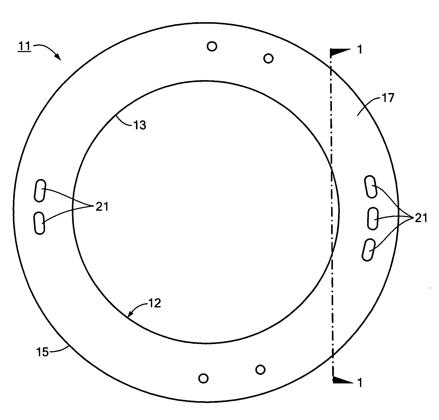
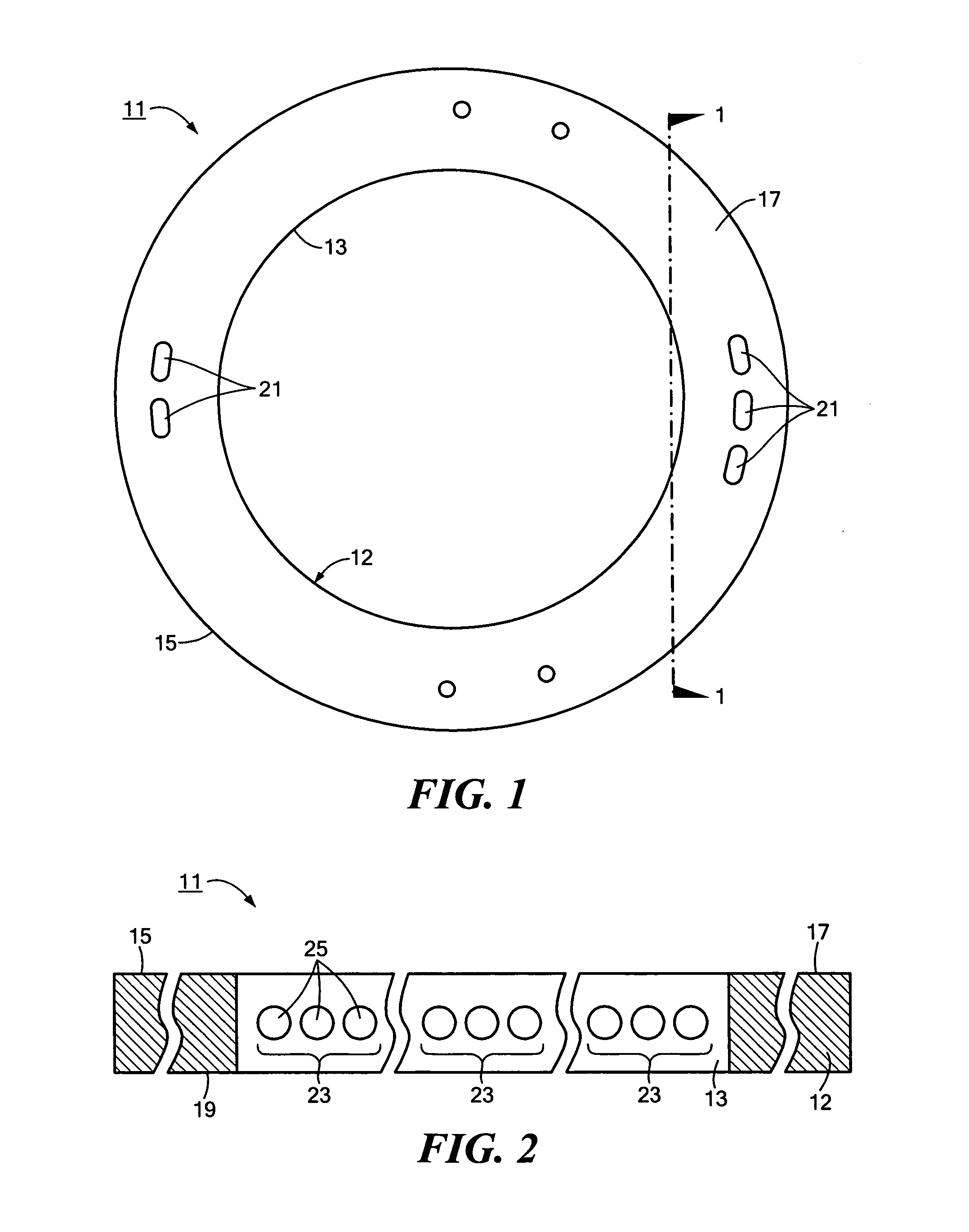
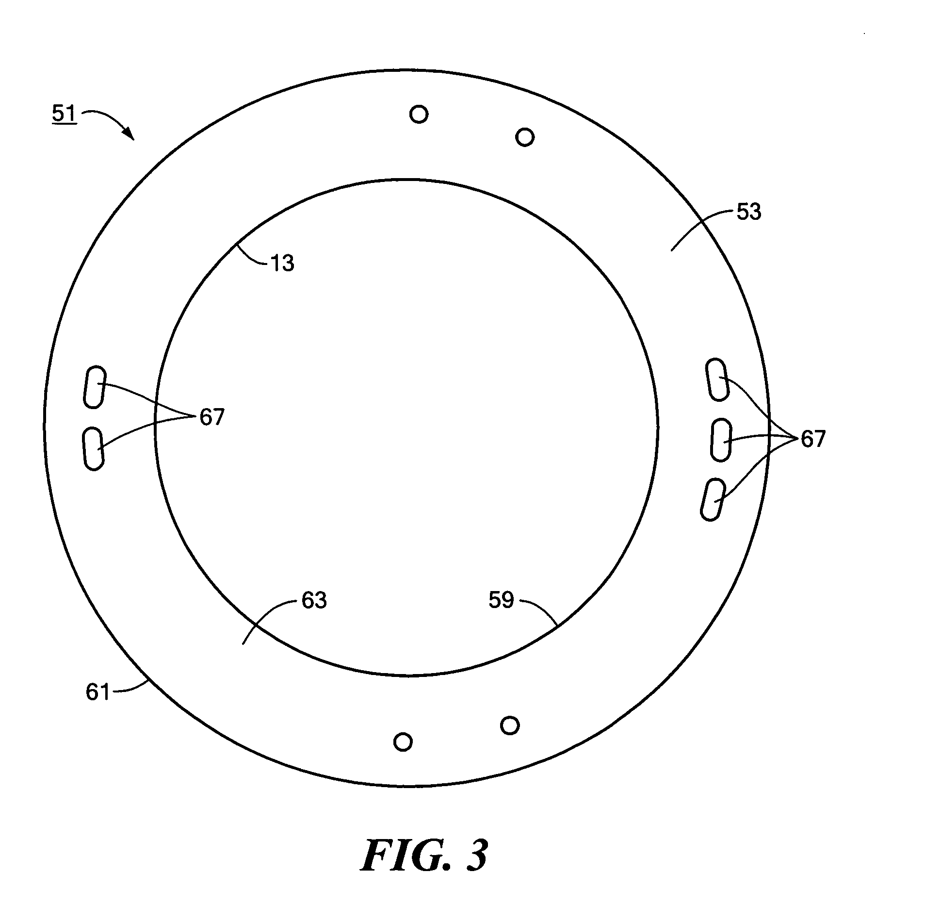
  • Cell frame for high-pressure water electrolyzer and method for manufacturing the same
  • Cell frame for high-pressure water electrolyzer and method for manufacturing the same
  • Cell frame for high-pressure water electrolyzer and method for manufacturing the same

Examples


example 1

Laminated and Integrated Cell Frame for High Pressure Water Electrolysis Operation:

[0064]The first step in fabricating the laminated and integrated cell frame for high pressure water electrolyzer operation was the development of an embossing mold capable of manufacturing the half-frame suitable for joining. This mold required several iterations to achieve success. First, we had to design slots (channels) that permitted the removal of the finished piece without ruining the part or the mold. This required the inclusion of appropriate draft angles in the channel region. The second iteration required a more careful angular alignment between the upper and lower halves of the embossing mold. Our first parts were not usable because the channels lined up below the sealing ribs and the welded part would have not sealed. We improved the mold design to properly locate the channels relative to the sealing ribs and allow easy part removal.

[0065]We then used the embossing mold to produce half-fra...

example 2

Unitized-Frame / Composite Ionomer Membrane or MEA:

[0067]The fabrication of a thin film ionomer membrane (or MEA) to frame-laminating process was performed. Recently, the present assigned has developed a novel proton exchange membrane ionomer structure that has demonstrated excellent mechanical properties. This dimensionally stable membrane (DSM™) comprises a thin plastic substrate (i.e., polysulfone) having millions of patterned (i.e., laser drilled) holes of 10 to 30 microns diameter that are imbibed or filled with an ionomer (i.e., NAFION perfluorocarbon sulfonic acid) to form a mechanically stable PEM thin film ionomer membrane. The edges of this composite membrane contain only the solid (no holes) plastic substrates while the “precursor electrochemically active” center area comprises the ionomer-filled holes. One of the important features of this composite DSM film is that the substrate can be made of the same mechanically stable thermoplastic (i.e., polysulfone) as the frame mat...


PUM

PropertyMeasurementUnit
Thicknessaaaaaaaaaa
Timeaaaaaaaaaa
Pressureaaaaaaaaaa

Abstract

Cell frame for high-pressure water electrolyzer and method of manufacturing the same. According to one embodiment, radial openings in a water electrolyzer frame are provided by laminating half-frames, one or both of which contains grooves that may be formed by molding, machining or die-cutting. Another to another embodiment, radial openings are provided by laminating three or more thin frame portions, the center piece of which may include transverse slots that may be made by molding, machining or die-cutting. According to yet another embodiment, two or more frame portions are provided, at least one of which includes a recess for receiving a porous structure. The frames of the present invention can be additionally laminated to the membrane and electrode assembly, as well as the bipolar separator plate in the perimeter or seal area, comprised of the same or similar material as the frame, to form unitized electrolyzer stack subassemblies or full assemblies.

Description

STATEMENT REGARDING FEDERALLY SPONSORED RESEARCH OR DEVELOPMENT[0001]The U.S. Government has a paid-up license in this invention and the right in limited circumstances to require the patent owner to license others on reasonable terms as provided for by the terms of Grant No. DE-FG02-06ER84537 awarded by the Department of Energy.CROSS-REFERENCE TO RELATED APPLICATIONS[0002]The present application claims the benefit under 35 U.S.C. 119(e) of U.S. Provisional Patent Application No. 61 / 126,493, filed May 5, 2008, the disclosure of which is incorporated herein by reference.BACKGROUND OF THE INVENTION[0003]The present invention relates generally to water electrolyzers and relates more particularly to a cell frame for a high-pressure (about 200 to 12,000 psi) water electrolyzer and to a method for manufacturing said cell frame.[0004]Water electrolysis is an important process for producing hydrogen, especially at remote sites, for electric generator cooling, materials processing, chemical r...

Claims


Application Information

Patent Timeline
IPC IPC(8): C02F1/461B23K20/10B29C65/00C25B9/00B23P11/00
CPCB29C65/02Y10T29/49826B29C65/08B29C65/14B29C65/1406B29C65/1412B29C65/1425B29C65/1477B29C65/1496B29C65/16B29C65/1612B29C65/1696B29C65/48B29C65/4895B29C66/348B29C66/54B29C66/7352B29C66/919B29C66/91933B29C2035/0822B29C2035/0827B29K2065/00B29K2071/12B29K2081/04B29K2081/06B29K2105/0079B29L2016/00B29L2024/006C02F1/46109C02F2001/46152C02F2201/46105C02F2201/46115C02F2201/4618C02F2201/46195C02F2301/066C25B9/206B29C65/1654B29C65/1677B29C66/543B29C66/91421B29C66/929B29C66/934B29C66/939Y10T156/10B29C65/04B29C66/73921B29C66/71B29C66/723C25B9/77
Inventor NORMAN, TIMOTHY J.MILGATE, ROBERT W.STONE, ROBERTSCHMITT, EDWIN W.LACONTI, ANTHONY B.
Owner GINER ELECTROCHEMICAL SYST LLC
Learn More