Stabilized UAV recovery system

Active Publication Date: 2009-12-03
ADVANCED TECH & RES CORP +1
View PDF4 Cites 135 Cited by
  • Summary
  • Abstract
  • Description
  • Claims
  • Application Information

AI Technical Summary

Benefits of technology

[0010]Prior to UAV recovery, the robot arm is positioned such that the capture mechanism is over the side of the ship and above the level of the deck. Using the sensed position of the UAV relative to the capture mechanism, the UAV is commanded along a flight path that passes below the capture mechanism such that the arresting hook would snag the arresting line. If there is wave-induced ship motion, the robot arm is commanded to compensate for the motion, holding the capture mechanism stable from the perspective of a UAV approaching from directly behind, or directly in front, of the mechanism. The robot arm controller relies on inputs provided by a ship motion sensor in order to provide the ship motion compensating commands to the robot arm actuators. If there is error relative to the commanded flight path, such as from wind-induced buffeting of the UAV, the capture mechanism is rotated via commands from the robot arm controller to compensate for the rapid vertical perturbations of the UAV about its commanded flight path during the final seconds prior to capture. To provide this compensation, the robot arm controller relies on input from the UAV position sensing system. This function is analogous to a baseball catc

Problems solved by technology

Adoption of UAVs for use aboard ships, however, is limited largely because of the challenges of recovery at sea.
The challenges include small flight decks and wave-induced ship motion.
Drawbacks to net-based capture include the risk of damage to the UAV and the potential for the UAV to be ensnared in the net.
Drawbacks to water landing include the necessity to modify the UAV heavily for water landings and the need to recover the UAV from the water after landing.
A drawback of the system disclosed in U.S. Pat. No. 7,059,564 is that the UAV must be designed to accommodate a severe turning moment caused by the arresting line force exerted on a wing tip.
This system has been successfully operated using small UAVs (i.e., under 5

Method used


Image

  • Stabilized UAV recovery system
  • Stabilized UAV recovery system
  • Stabilized UAV recovery system

Examples


Embodiment Construction

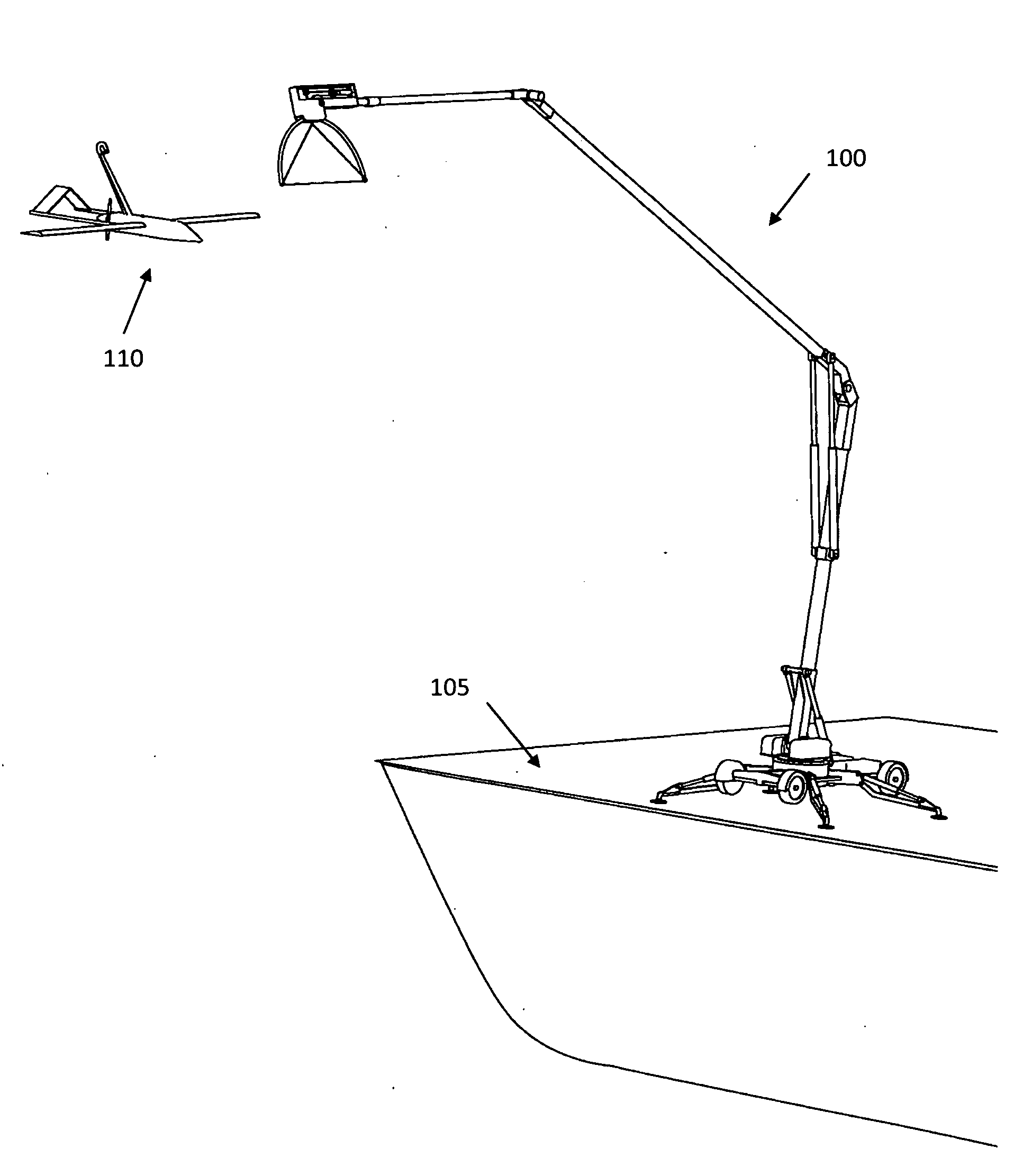
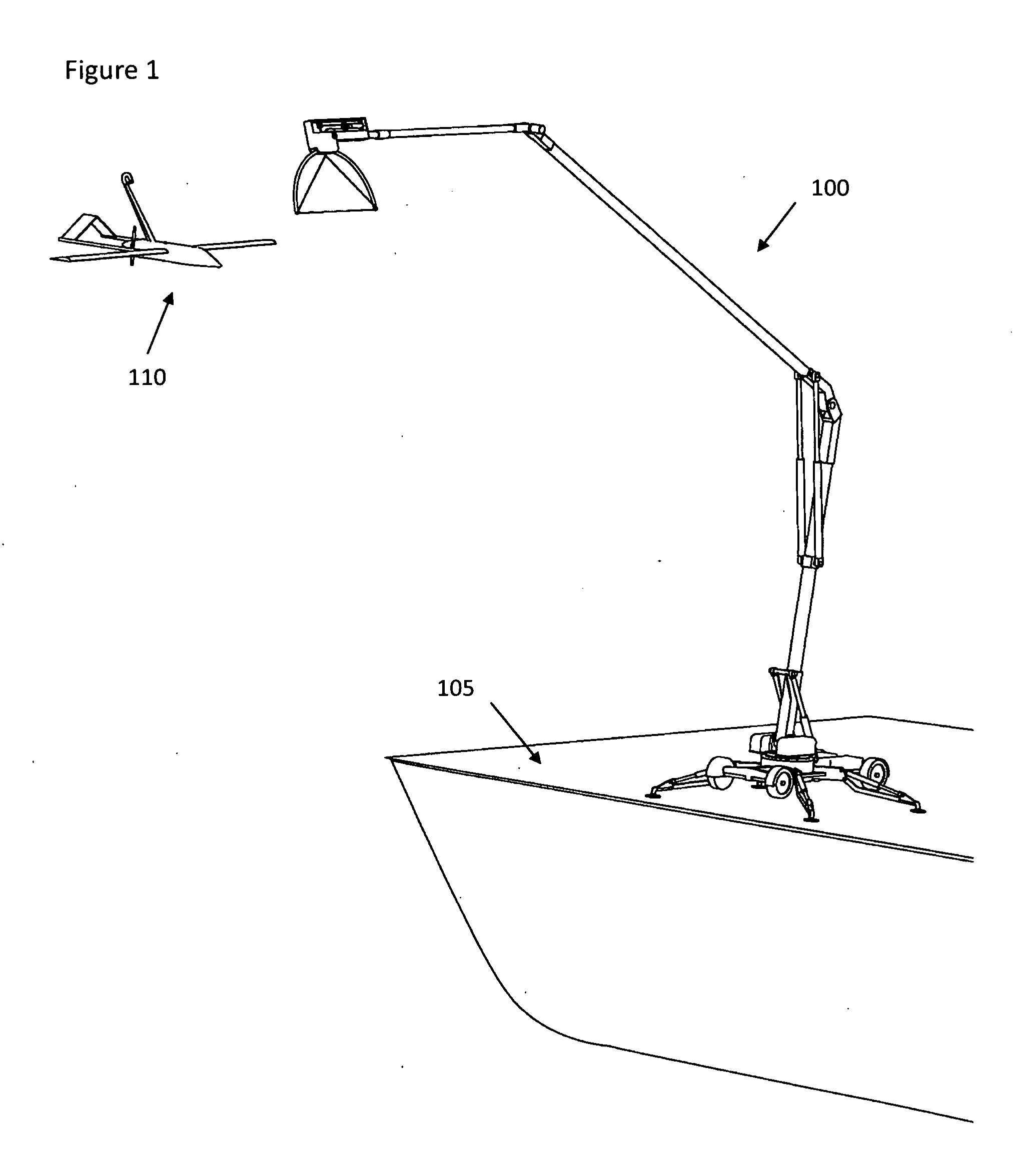
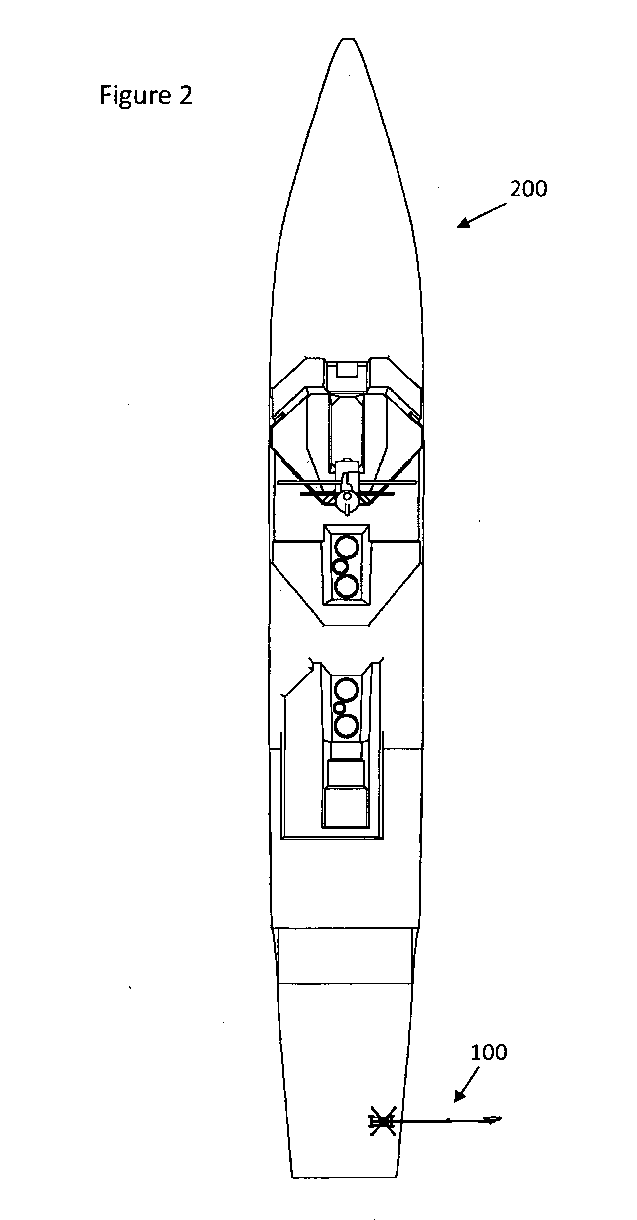
[0028]FIG. 1 depicts the stabilized UAV recovery system in accordance with the illustrative embodiment of the present invention. In the illustrative embodiment, UAV recovery system 100 is mounted to deck 105 of a ship to recover UAV 110 at sea. FIG. 2 shows the relative location of UAV recovery system 100 on ship 200. In some other embodiments, the UAV recovery system, with some modification, is mounted to a ground vehicle and used to recover UAVs over land.

[0029]FIG. 3 depicts the major components of the UAV recovery system 100. These components include computer-controlled robot arm 300 and capture mechanism 305. In a fashion similar to aircraft arrest systems on aircraft carriers, capture mechanism 305 presents arresting line segment 310, which is held horizontally, to incoming UAV 110 that is snagged by arresting hook 315 mounted to UAV 110. Arresting line segment 310 is held between two curved posts 320 of the capture mechanism. In contrast to aircraft arrest systems on aircraft...


PUM


Abstract

A stabilized UAV recovery system is disclosed. In the illustrative embodiment for UAV recovery over water, the system includes ship-based elements and UAV-based elements. The ship-based elements include a robot arm that holds a capture mechanism over the side of the ship while compensating for wave-induced ship motion. The UAV-based elements include a hook mounted to the top of the UAV fuselage. With the capture mechanism held stable from the perspective of a UAV approaching from behind or in front of the mechanism, the UAV is flown under it, snagging an arresting line with the hook. With continued forward motion of the UAV, the arresting line pulls out of a winch drum that is coupled to a brake, bringing the UAV to rest.

Description

RELATED U.S. APPLICATION DATA[0001]Provisional Application No. 61 / 130,699, filed Jun. 2, 2008.FEDERALLY SPONSORED RESEARCH[0002]The invention that is the subject of this application was developed with federal funding through to the Small Business Innovation Research (SBIR) program. Accordingly, the applicant retains its rights to the intellectual property created, subject to the standard patent rights clause as set forth in the Code of Federal Regulations at 37 CFR 401.14. Under this clause the U.S. Government has a nonexclusive, nontransferable, irrevocable, royalty-free license to practice the invention for U.S. Government purposes only.FIELD OF THE INVENTION[0003]The present invention relates to systems for recovering unmanned aerial vehicles (UAVs).BACKGROUND OF THE INVENTION[0004]UAVs are widely used for military and non-military uses. Roles for UAVs include reconnaissance and offensive strike missions. Adoption of UAVs for use aboard ships, however, is limited largely because ...

Claims


Application Information

Patent Timeline
IPC IPC(8): B64F1/02G05D1/00
CPCB63B27/10B64C2201/182B64C2201/205B64C39/024B64U70/30B64U80/84
Inventor LOVELL, GILBERTHUI, ERIC CHI-KAIUMBREIT, MERRILL KEITH
Owner ADVANCED TECH & RES CORP
Why Eureka
Try Eureka