Radiation imaging apparatus, its control method, and recording medium storing program for executing the control method

a technology of imaging apparatus and control method, applied in the direction of radiation controlled devices, instruments, optical radiation measurement, etc., can solve the problems of ineffective refresh operation and inability to obtain stable image quality, and achieve the effect of reducing the fluctuation or image uncomfortable feeling of image luminance, reducing the sensitivity change of a conversion element, and reducing the sensitivity of the conversion elemen

Active Publication Date: 2009-12-03
CANON KK
View PDF35 Cites 18 Cited by
  • Summary
  • Abstract
  • Description
  • Claims
  • Application Information

AI Technical Summary

Benefits of technology

[0009]It is an object of the present invention to provide an imaging apparatus capable of restraining a change of image qualities due to a change of sensitivities of a photoelectric conversion element and its control method.
[0010]According to the

Problems solved by technology

However, a state in which a refresh operation is not effective is present in an MIS-ty

Method used


Image

  • Radiation imaging apparatus, its control method, and  recording medium storing program for executing the control method
  • Radiation imaging apparatus, its control method, and  recording medium storing program for executing the control method
  • Radiation imaging apparatus, its control method, and  recording medium storing program for executing the control method

Examples


first embodiment

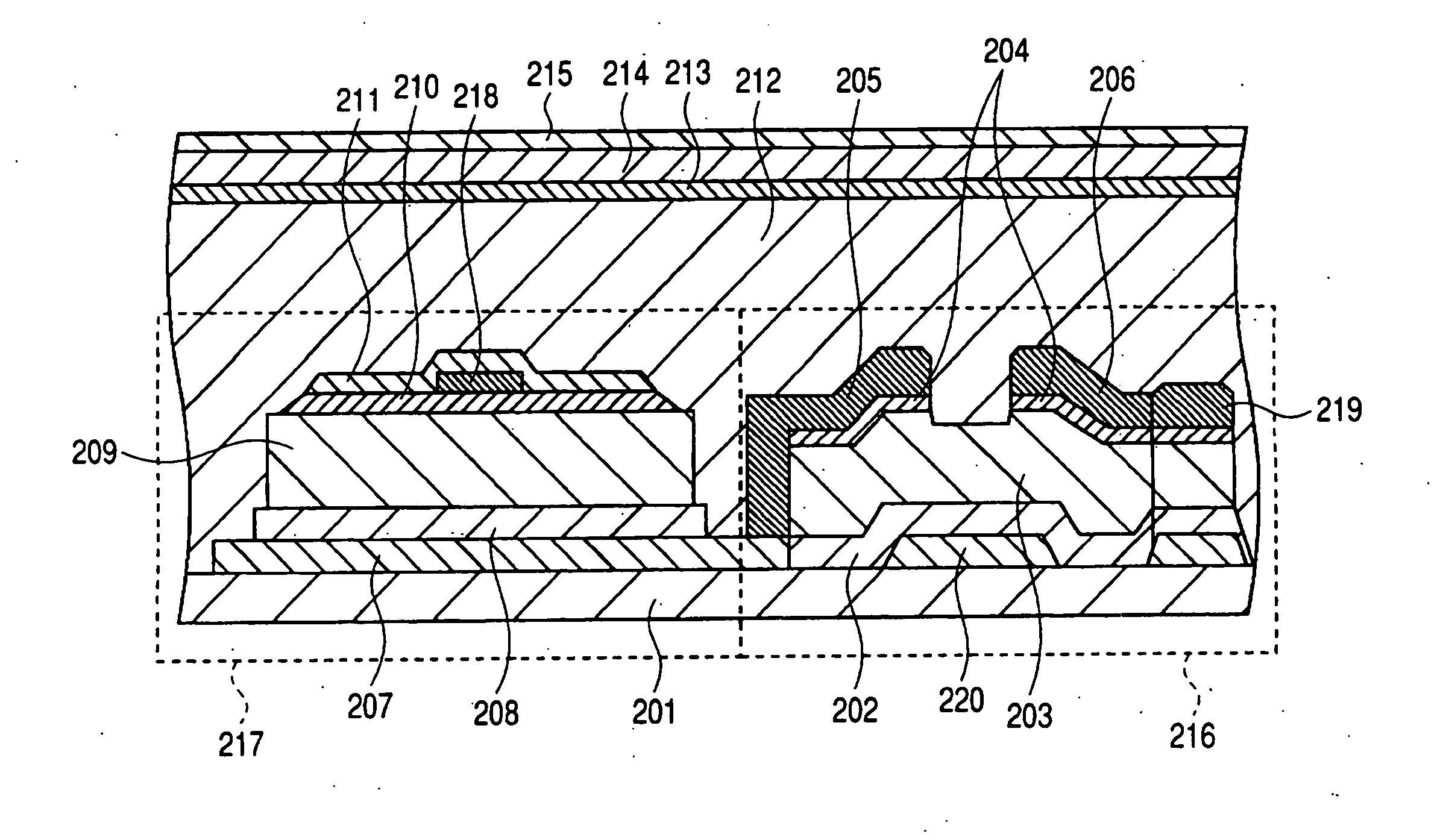
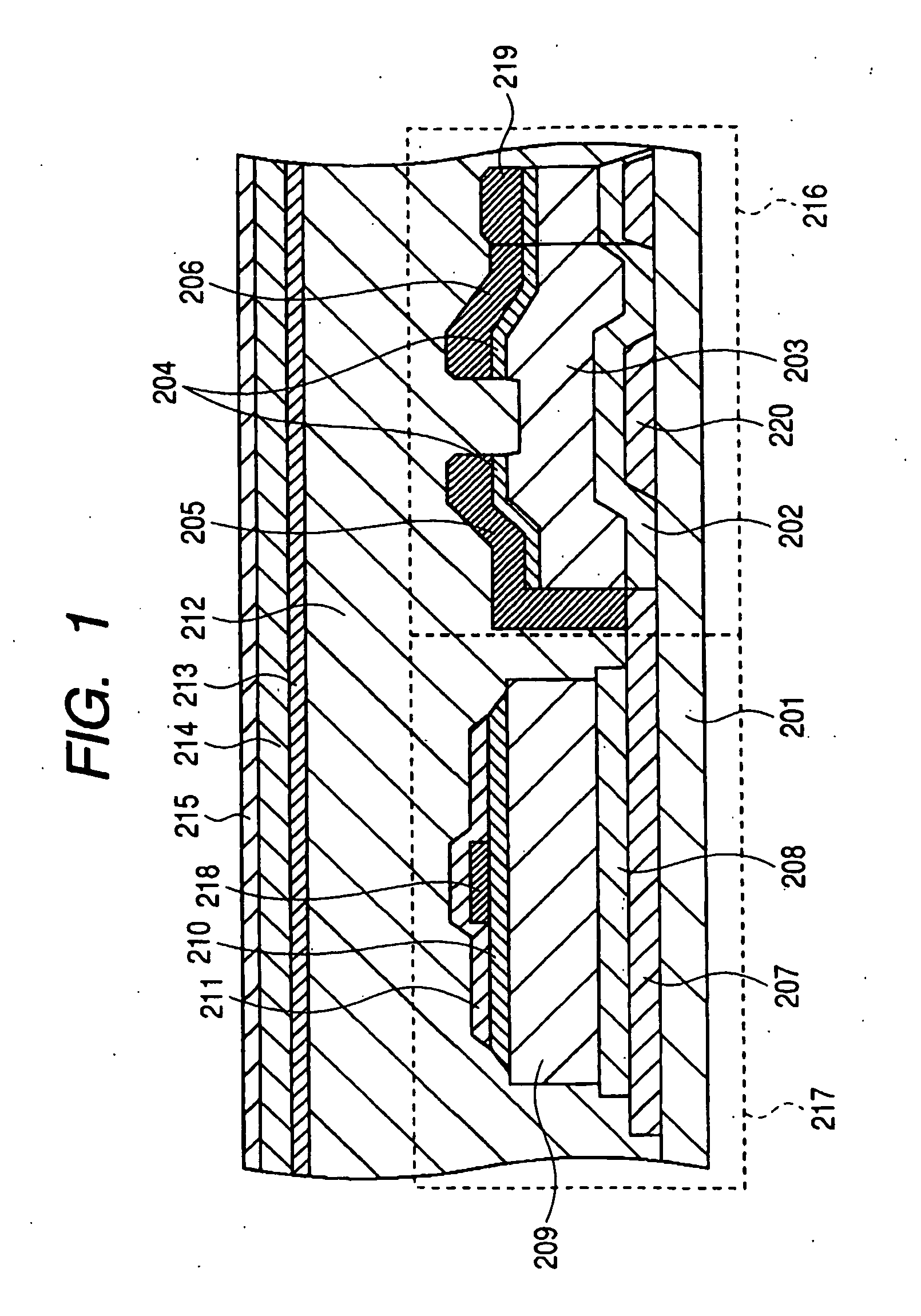
[0062]First, first embodiment of the present invention is described below. FIG. 5 is a circuit diagram showing the configuration of one pixel of a two-dimensional sensor (sensor unit) in a radiation imaging apparatus (X-ray imaging apparatus) of the first embodiment of the present invention. In FIG. 5, a component provided with the same symbol as that in FIG. 1, 3 or the like is a device or circuit having the same function and its description is omitted.

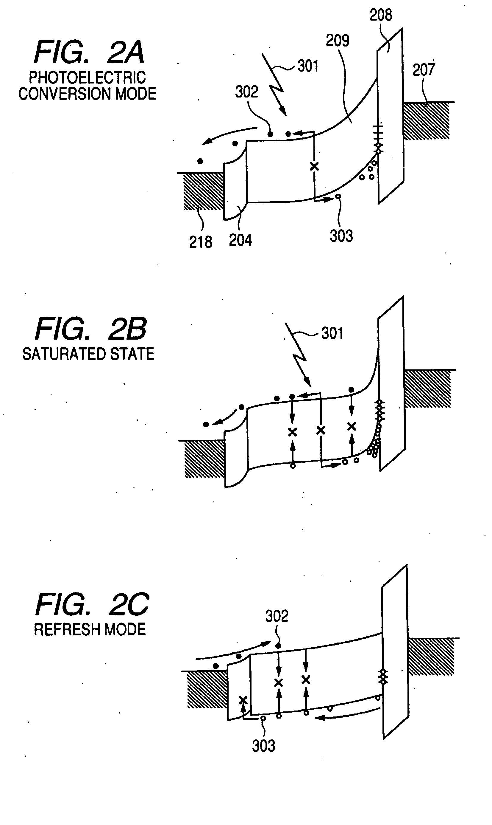
[0063]This embodiment is provided with a light source 601, power supply 603 for making the light source 601 emit light, and switch 605 as means for bringing the MIS-type photoelectric conversion element 217 into a saturation state before performing X-ray imaging. As the light source 601, it is possible to use a light source capable of discharging the light having a wavelength which can be detected by the photoelectric conversion layer 209 serving as the conversion layer of an MIS-type conversion element at optional timing. For exampl...

second embodiment

[0111]Then, second embodiment of the present invention is described below. FIG. 11 is a circuit diagram showing the configuration of one pixel of the two-dimensional sensor of the radiation imaging apparatus (X-ray imaging apparatus) of the second embodiment of the present invention.

[0112]To image a dynamic image, it is necessary that a photoelectric conversion element always keeps stable sensitivity and dynamic range. Therefore, it is preferable to refresh pixels every frame. However, in the case of the structure of the first embodiment, refresh can be simultaneously performed only for all pixels. Therefore, a frame rate is lowered by the time of the refresh operation.

[0113]However, in the case of the second embodiment, a TFT 1004 for refresh is set every pixel. The gate of the TFT 1004 for refresh is connected to a gate line 1006 connected to a vertical driving circuit 1001. Moreover, the source of the TFT 1004 for refresh is connected to the source of the TFT 216 and a refresh po...


PUM


Abstract

To provide a radiation imaging apparatus capable of restraining the change of image qualities due to the change of sensitivities of an MIS-type photoelectric conversion element and its control method. Therefore, an MIS-type photoelectric conversion element 217 is set to a saturation state before performing radiation imaging. As means for realizing the above mentioned, a light source 601, power supply 603 for making the light source 601 emit light, and switch 605 are provided. The light source 601 can use a light source capable of discharging the light having a wavelength which can be detected by a photoelectric conversion layer 209 at optional timing. For example, it is possible to use a light source in which a plurality of LEDs or cold cathode ray tubes are arranged, a light guide plate is combined with an LED or cold cathode ray tube, or an EL device.

Description

TECHNICAL FIELD[0001]The present invention relates to a radiation imaging apparatus to be preferably used for diagnosis for medical care and industrial non-destructive inspection and its control method. In the case of the present invention, it is assumed that electromagnetic waves such as X ray and y ray and α ray and β ray are included in radiation.BACKGROUND ART[0002]In recent years, an X-ray digital imaging apparatus for performing imaging by using a converter such as a photoelectric transducer for converting light into an electrical signal and thereby using radiation such as X ray is practically used and spread in accordance with the advancement of semiconductor technology.[0003]Because a digital X-ray imaging apparatus has a sensitivity and image quality superior to those of a conventional film-type imaging apparatus, imaging at lower dose and improvement of diagnosability are possible. Moreover, because an image is stored as digital data, there are advantages that the image ca...

Claims


Application Information

Patent Timeline
IPC IPC(8): G01T1/24G01J1/32
CPCH01L27/14676G01T1/2018H04N5/32G01T1/2006
Inventor YAGI, TOMOYUKIENDO, TADAOKAMESHIMA, TOSHIOTAKENAKA, KATSUROYOKOYAMA, KEIGO
Owner CANON KK
Why Eureka
Try Eureka