Fluorescent temperature sensor

a technology of fluorescence and temperature sensor, which is applied in the direction of instruments, heat measurement, measurement devices, etc., can solve the problems of neither complex connection nor complex adjustment, and achieve the effect of stabilizing temperature measuremen

Inactive Publication Date: 2009-12-03
YAMATAKE HONEYWELL CO LTD
View PDF23 Cites 20 Cited by
  • Summary
  • Abstract
  • Description
  • Claims
  • Application Information

AI Technical Summary

Benefits of technology

[0011]Given the fluorescent temperature sensor according to the second invention, the light conveying media are optical fibers (optical fiber strands), and when light is conveyed by an optical fiber bundle that is a bundle of a plurality of these optical fiber strands, it is possible to cause the light that is produced by the light projecting element to be illuminated reliably into the core of the optical fiber, through positioning the cores of a portion of the optical fibers that structure the optical fiber bundle for the projected light to be within the range of the directional characteristics of the light projecting element. On the other hand, it is possible to cause the fluorescent light that is produced by the fluorescent material to be emitted reliably onto the light receiving element through positioning the light receiving element within the scope of the aperture angle of a portion of the optical fibers that structure the optical fiber bundle for the received light. This simple structure enables the light to be conveyed reliably, and enables the intensity of the fluorescent light of the fluorescent material to be caused to be uniform, making it possible to achieve stabilized temperature measurements.

Problems solved by technology

Because of this, these bundles of light conveying media need only be aligned to the fluorescent material, so neither the connection nor the adjustments are complex.

Method used


Image

  • Fluorescent temperature sensor
  • Fluorescent temperature sensor
  • Fluorescent temperature sensor

Examples


Embodiment Construction

[0017]A fluorescent temperature sensor will be explained as one example of embodiment according to the present invention, in reference to FIG. 1 through FIG. 5.

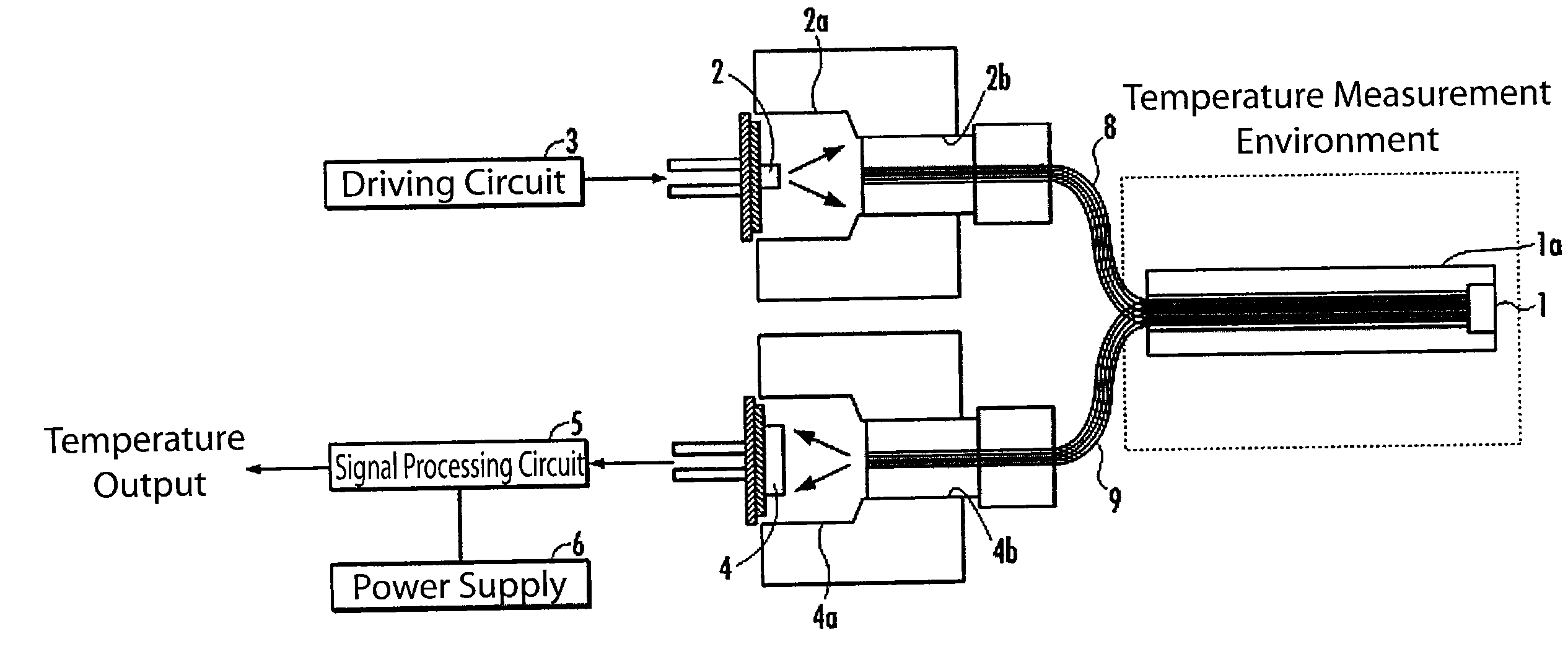
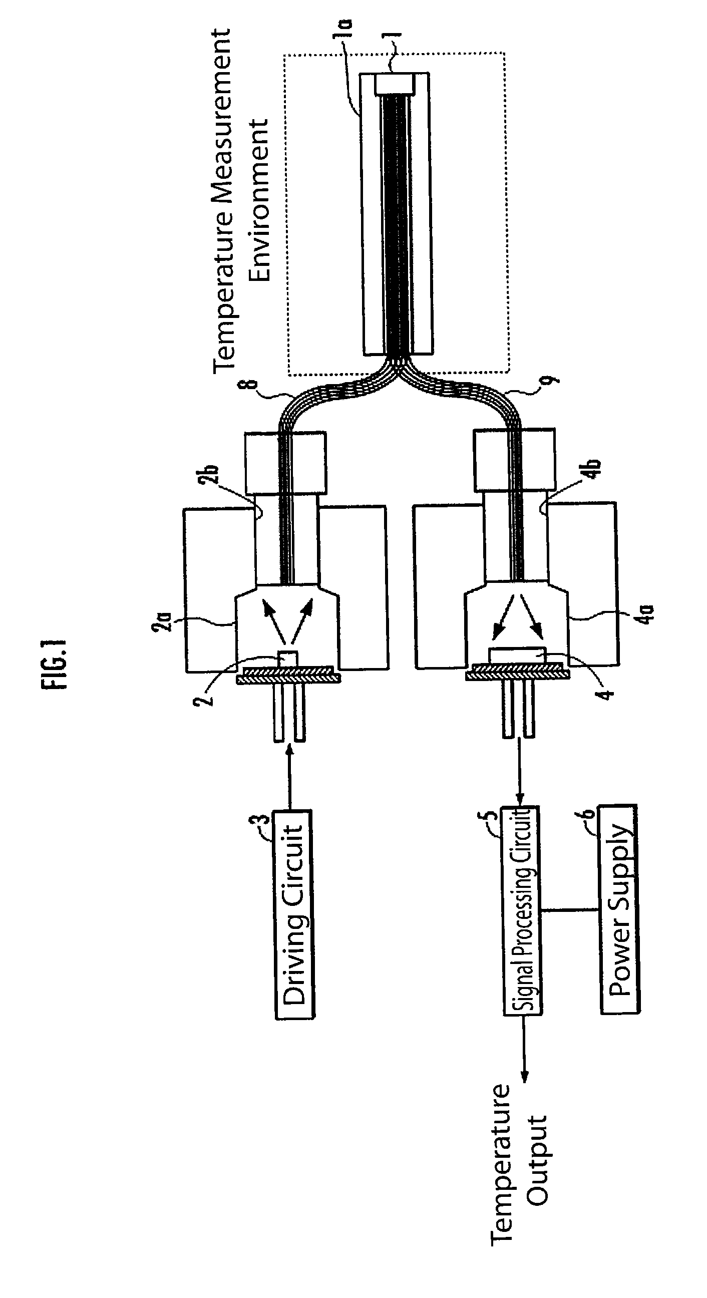
[0018]The overall structure of the fluorescent temperature sensor according to the present embodiment will be explained in reference to FIG. 1. The fluorescent temperature sensor is provided with a fluorescent material 1 that exhibits fluorescent characteristics that vary with temperature, an LED 2 as a light projecting element for projecting light to the fluorescent material 1, a driving circuit 3 for driving the LED 2, and a photodiode 4, as the light receiving element, for receiving the fluorescent light that is emitted by the fluorescent material 1. Furthermore, a power supply 6 is connected to a signal processing circuit 5, and the electric power that is required for the operation of the fluorescent temperature sensor is provided by the power supply 6. Furthermore, the fluorescent temperature sensor is provided with opti...


PUM

PropertyMeasurementUnit
light emission timeaaaaaaaaaa
temperatureaaaaaaaaaa

Abstract

To use a simple structure to provide a fluorescent temperature sensor with increased accuracy through increasing the fluorescent light intensity of the fluorescent materials. A fluorescent temperature sensor for producing a temperature signal from a fluorescent light of a fluorescent material that is optically stimulated is provided with an LED for projecting light onto the fluorescent material, a photodiode for receiving the fluorescent light that is emitted by the fluorescent material, and a signal processing circuit for generating the temperature signal from the output of the photodiode. Optical fibers for the projected light, for conveying the light from the LED to the fluorescent material, and optical fibers for the received light, for conveying the light from the fluorescent material to the photodiode, are separated and independent from each other on one end side thereof, facing the respective elements, and on the other end side, which faces the fluorescent material, are bundled so as to be mixed together.

Description

CROSS REFERENCE TO PRIOR APPLICATIONS[0001]The present application claims priority under U.S.C. §119 to Japanese Patent Application No. 2008-138299, filed May 27, 2008. The content of the application is incorporated herein by reference in its entirety.FIELD OF TECHNOLOGY[0002]The present invention relates to a fluorescent temperature sensor for generating a temperature signal from fluorescent light of a fluorescent material that is optically stimulated.BACKGROUND OF THE INVENTION[0003]As an example of this type of fluorescent temperature sensor, there is the known example of a light source and a light receiving element being spatially separated, as illustrated in U.S. Pat. No. 5,470,155. In this type of fluorescent temperature sensor, the other end of an optical fiber wherein one end faces a fluorescent material is both illuminated by the light from a light source, through a half mirror or a dichroic mirror, and the fluorescent light that is produced by the fluorescent material illu...

Claims


Application Information

Patent Timeline
Patent Type & Authority Applications(United States)
IPC IPC(8): G01K11/00
CPCG01K11/3213
Inventor KINUGASA, SEIICHIROKATO, ATSUSHI
Owner YAMATAKE HONEYWELL CO LTD
Why Eureka
Try Eureka