Software defined base station

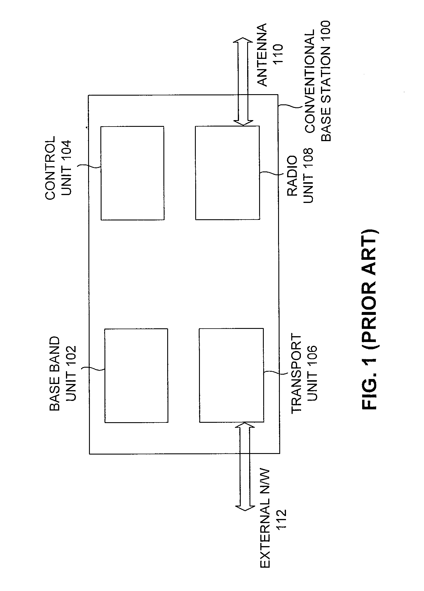
a software defined and base station technology, applied in the field of wireless communication, can solve the problems of large size of the base station b>100/b>, high cost, and insufficient flexibility of the existing software defined radio architecture, and achieve the effect of increasing the overall network capacity, cost-effective and flexibl

Inactive Publication Date: 2009-12-03
SLOKA TELECOM PVT
View PDF5 Cites 13 Cited by
  • Summary
  • Abstract
  • Description
  • Claims
  • Application Information

AI Technical Summary

Benefits of technology

[0012]Accordingly, there remains a need for a base station to increase overall network capacity with ease of deployment, management, upgrade, maintenance and provide cost-effective and flexible solutions that can accommodate multiple technologies across a wider frequency band of operation.

Problems solved by technology

Each base station may broadcast a signal to a limited range due to having limited signal strength.
Since each of the units (e.g., the base band 102, the control unit 104) is built as an independent piece of hardware, the resulting base station 100 is large in size, intensive in hardware requirements, and expensive.
However, current solutions are inadequate because they are limited to transceiver architectures.
The extent of flexibility introduced by existing Software Defined Radio architectures is limited to radio and some aspects of baseband.
Such architectures are not fully configurable in the sense of flexible design, component reuse and cost savings.
With this increase in the number of installed base stations, the high cost of conventional base stations compounds capital expenditure and operating expenditure for operators.
Also the maintenance (e.g., upgrade, troubleshooting) costs are high since a service man may have to travel to visit each base station for maintenance work.
Further, design, development, implementation and testing times are high due to long hardware cycles resulting in a large time-to-market.

Method used


Image

  • Software defined base station
  • Software defined base station
  • Software defined base station

Examples


Embodiment Construction

[0031]The embodiments herein and the various features and advantageous details thereof are explained more fully with reference to the non-limiting embodiments that are illustrated in the accompanying drawings and detailed in the following description. Descriptions of well-known components and processing techniques are omitted so as to not unnecessarily obscure the embodiments herein. The examples used herein are intended merely to facilitate an understanding of ways in which the embodiments herein may be practiced and to further enable those of skill in the art to practice the embodiments herein. Accordingly, the examples should not be construed as limiting the scope of the embodiments herein.

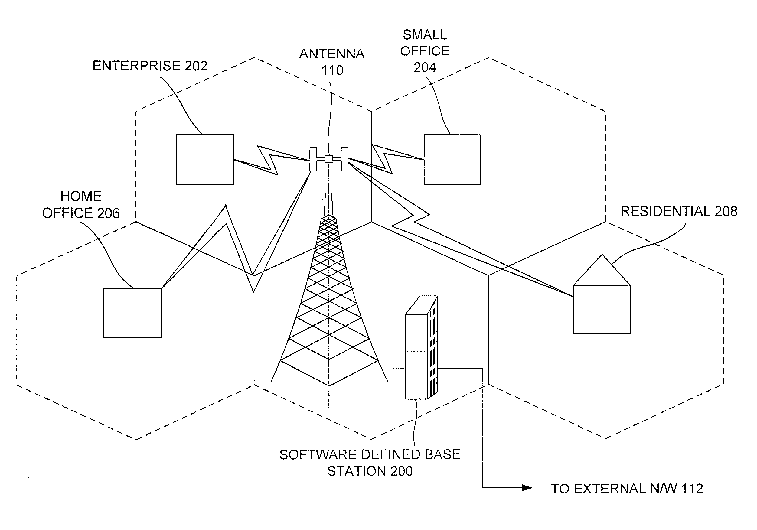
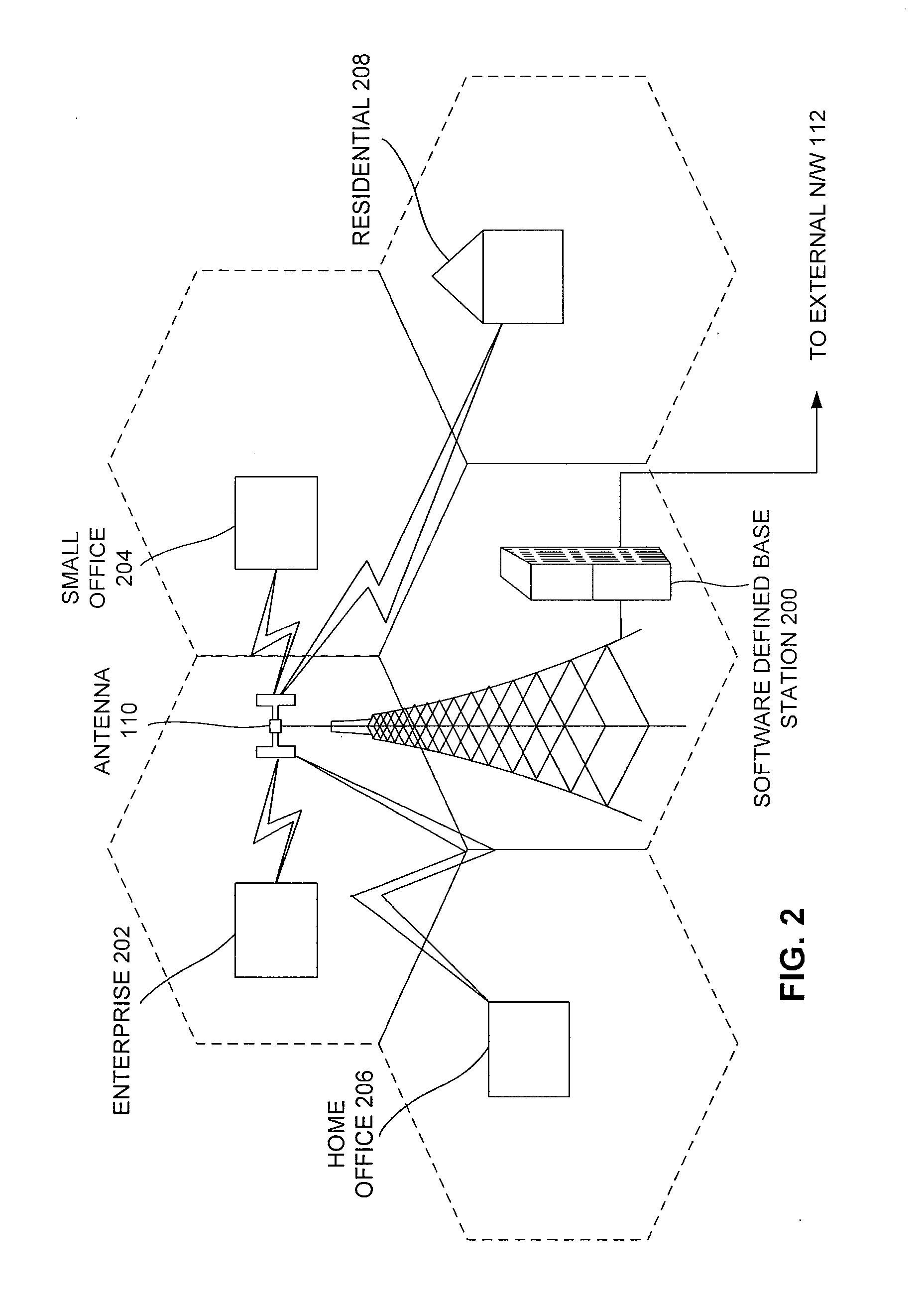
[0032]As mentioned, there remains a need for a base station to increase overall network capacity with ease of deployment, management, upgrade, maintenance and provide cost-effective and flexible solutions that can accommodate multiple technologies across a wider frequency band of operation. The...


PUM


Abstract

A system of base station includes a common controller platform to integrate a controller specific softwares of at least two technologies, a common transport platform to integrate a transport specific softwares of at least two technologies, a common base station software to interface with the common controller platform and the common transport platform, a generic hardware to execute the common controller platform and the common transport platform, and a plurality of hardware specific API to interface and communicate between the common software base station and the generic hardware. The common base station software includes, a common controller interface module to generate communication between the plurality of hardware specific API and the common controller platform, and a common transport interface module to generate communication between the plurality of hardware specific API and the common transport platform.

Description

RELATED APPLICATIONS[0001]This application is a continuation under 35 U.S.C. 111(a) of PCT / IN2008 / 000091, filed Feb. 15, 2008 and published as WO 2008 / 099425 A2 on Aug. 21, 2008, which claimed priority under U.S.C. 119 to India Patent Application No. 318 / CHE / 2007, filed Feb. 16, 2007, which applications and publication are incorporated herein by reference and made a part hereof.BACKGROUND[0002]1. Technical Field[0003]The embodiments herein generally relate to wireless communication and more particularly to a software defined base station.[0004]2. Description of the Related Art[0005]A base station is a hardware device that works as a communicating entity with multi-channel two-way radio front-end in a mobile communication network. The base station may work as a representative of one or more network service (e.g., mobile communication service, internet service) providers, as a central radio transmitter / receiver that maintains communications with wireless devices (e.g., mobile phones, ...

Claims


Application Information

Patent Timeline
Patent Type & Authority Applications(United States)
IPC IPC(8): H04M1/00G06F3/00H04W24/02H04W88/10
CPCH04W88/10H04W24/02
Inventor KARAMPURI, SUJAI
Owner SLOKA TELECOM PVT
Why Eureka
Try Eureka