Dressing assemblies for wound treatment using reduced pressure

a wound treatment and reduced pressure technology, applied in the field of medical treatment systems, can solve the problems of affecting the healing effect of damaged tissue, affecting the healing effect of wounds, and requiring time and care to heal, so as to achieve uniform distribution of compressive force and reduce pressure

Active Publication Date: 2009-12-03
3M INNOVATIVE PROPERTIES CO
View PDF101 Cites 91 Cited by
  • Summary
  • Abstract
  • Description
  • Claims
  • Application Information

AI Technical Summary

Benefits of technology

[0007]Shortcomings with aspects of wound care are addressed by the illustrative embodiments herein. According to one illustrative embodiment, a dressing assembly for use with a reduced pressure treatment system includes a shaped dressing bolster, which has a first surface, a second (inward-facing) surface, and an extremity. The shaped dressing bolster is formed from a medical bolster material. The extremity has an oblique surface. The shaped dressing bolster is operable to evenly distribute a compressive force.
[0008]According to another illustrative embodiment, a dressing assembly for use with a reduced-pressure treatment system includes a shaped dressing bolster, which has a first surface, a second (inward-facing) surface, and an extremity. The shaped dressing bolster is formed from a medical bolster material operable to distribute reduced pressure. The dressing assembly further includes an over-drape that is coupled to the first surface of the shaped dressing bolster and the extremity of the shaped dressing bolster. The shaped dressing bolster is operable to evenly distribute a compressive force that results when the shaped dressing bolster is subjected to reduced pressure.

Problems solved by technology

The damaged tissue will need time and care to heal and poses a number of potential complications and risks including edema, seroma, hematoma, further bruising, and ecchymosis to name some.
These devices are at times uncomfortable, may apply compression in a non-uniform manner, and can be difficult to take off and put on.
In addition, because of edema, a number of different compression garments may be required for a single patient.

Method used


Image

  • Dressing assemblies for wound treatment using reduced pressure
  • Dressing assemblies for wound treatment using reduced pressure
  • Dressing assemblies for wound treatment using reduced pressure

Examples


Embodiment Construction

[0031]In the following detailed description of the preferred embodiments, reference is made to the accompanying drawings that form a part hereof, and in which is shown, by way of illustration, specific embodiments in which the invention may be practiced. These embodiments are described in sufficient detail to enable those skilled in the art to practice the invention, and it is understood that other embodiments may be utilized and that logical structural, mechanical, electrical, and chemical changes may be made without departing from the spirit or scope of the invention. To avoid detail not necessary to enable those skilled in the art to practice the invention, the description may omit certain information known to those skilled in the art. The following detailed description is, therefore, not to be taken in a limiting sense, and the scope of the present invention is defined only by the appended claims.

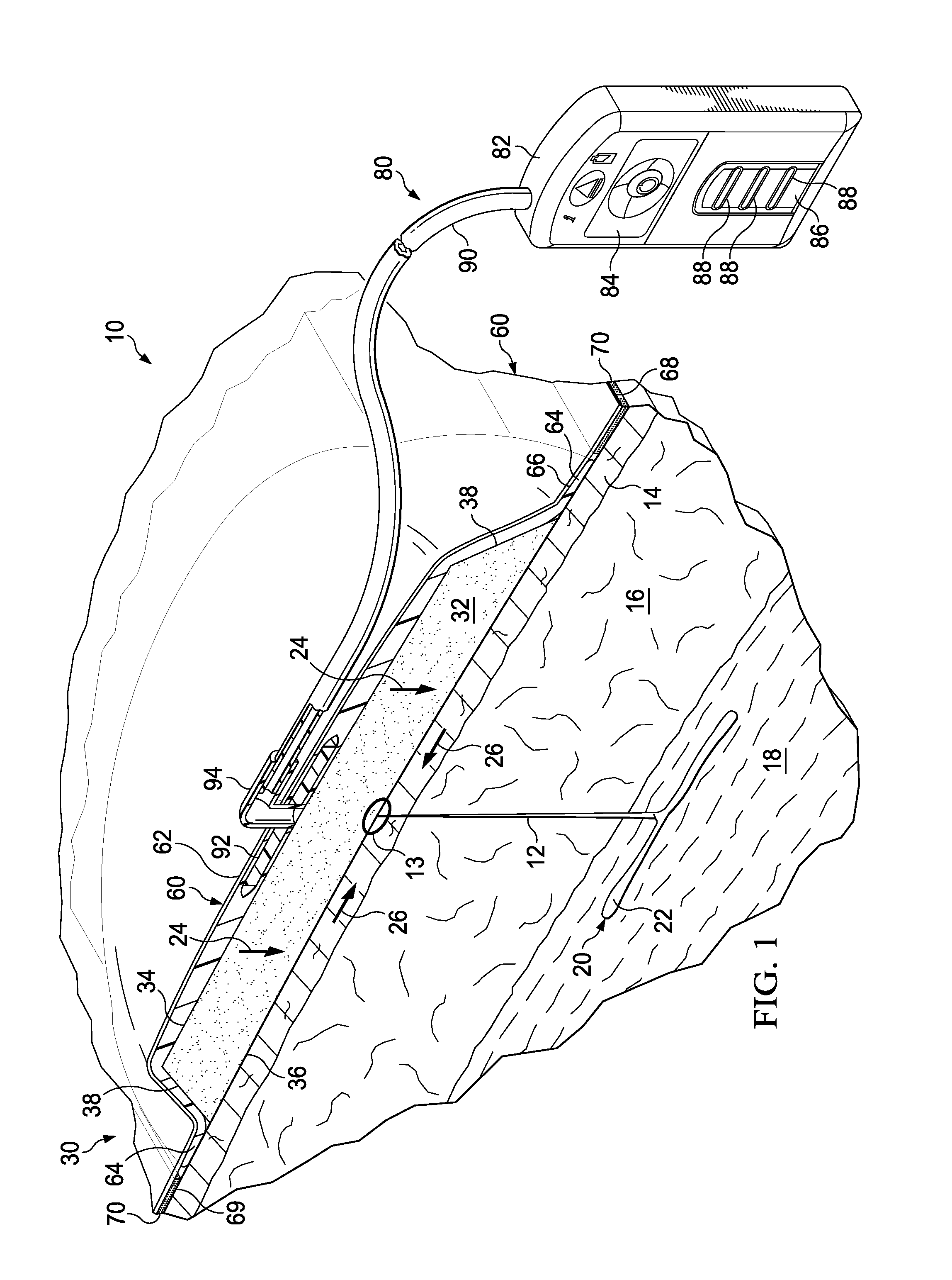
[0032]Referring now to FIG. 1, a reduced-pressure system 10 for treating tissue, su...


PUM

PropertyMeasurementUnit
densityaaaaaaaaaa
angle alphaaaaaaaaaaa

Abstract

A dressing assembly for use with a reduced pressure treatment system, the dressing assembly develops a directed force under reduced pressure. The directed force may be a radial force or a closing force. The dressing assembly includes a shaped dressing bolster having a shaped extremity that is operable to evenly deliver the radial force and to distribute reduced pressure. Numerous shapes may be used for the shaped extremity. The dressing assembly may further include an over-drape to assist in creating a seal over the shaped dressing bolster and against a portion of a patient's epidermis.

Description

RELATED APPLICATIONS[0001]The present invention claims the benefit, under 35 USC §119(e), of the filing of U.S. Provisional Patent Application Ser. No. 61 / 057,807, entitled “Reduced-pressure Surgical Wound Treatment System,” filed May 30, 2008; U.S. Provisional Patent Application Ser. No. 61 / 057,798, entitled “Dressing Assembly For Subcutaneous Wound treatment Using Reduce Pressure,” filed May 30, 2008; U.S. Provisional Patent Application Ser. No. 61 / 057,808, entitled “See-Through, Reduced-Pressure Dressing,” filed May 30, 2008; U.S. Provisional Patent Application Ser. No. 61 / 057,802, entitled “Reduced-Pressure Dressing Assembly For Use in Applying a Closing Force,” filed May 30, 2008; U.S. Provisional Patent Application Ser. No. 61 / 057,803, entitled “Reduced-Pressure, Linear-Wound Treatment System,” filed May 30, 2008; U.S. Provisional Patent Application Ser. No. 61 / 057,800, entitled “Reduced-Pressure, Compression System and Apparatus for use on a Curved Body Part,” filed, May 30, ...

Claims


Application Information

Patent Timeline
Patent Type & Authority Applications(United States)
IPC IPC(8): A61M27/00
CPCA61L15/60Y10T29/49826A61M1/0088A61F13/00068A61F13/022A61F13/0223A61F13/0243A61F2013/00174A61F2013/00536A61F2013/0054A61F2013/00748A61F13/0209A61F13/0216A61H1/008A61F13/0289A61F13/00038A61F2013/00131A61F2013/0028A61F13/00029A61F13/00034Y10T29/49A61M1/0023A61M1/916A61M1/71A61M1/915A61M2210/1007A61M2210/1021A61F13/00A61F15/008A61M1/917A61F13/00017A61F2013/00182A61M2207/00A61F2013/00136A61F13/00059A61M2205/70A61F2013/00246H05K999/99
Inventor KAZALA, JR., RICHARD MARVINLONG, JUSTIN ALEXANDERBARTA, ERIC WOODSONYAO, LIWILKES, ROBERT PEYTON
Owner 3M INNOVATIVE PROPERTIES CO
Why Eureka
Try Eureka