Prosthetic limb

a technology for prosthetic limbs and limbs, applied in the field of prosthetic limbs, can solve the problems of not readily available to people, little thought given to the aesthetics of the human being for whom the device was intended, and many people do not have access to prosthetic limb manufacturers, etc., to achieve the effect of reducing rotational friction due to sliding components, reducing friction, and running more efficiently

Active Publication Date: 2009-12-03
3D SYST INC
View PDF18 Cites 36 Cited by
  • Summary
  • Abstract
  • Description
  • Claims
  • Application Information

AI Technical Summary

Benefits of technology

[0011]The knee and ankle of the prosthetic leg may have sliding connections at the knee and ankle. In order to minimize the friction, lubricants can be used at these connection points. Alternatively, lower friction bearings or bushings can be used at these rotating connections. In an embodiment, the bearings such as ball or roller can be placed in small indentations or recesses in the knee or ankle that function as races or sliding surfaces for the bearings. By inserting the bearings, the rotational friction due to the sliding components is reduced.
[0012]In an embodiment, the user's intact foot is scanned and used in the design of the prosthetic leg. In another embodiment, the intact foot is measured but not scanned. Rather than fabricating a mirror image foot, a stock foot design that may have a matching length and width is retrieved from a database. The retrieved design data is then integrated into the prosthetic leg design and fabricated simultaneously with the rest of the leg. In yet another alternative embodiment, the feet are stock items that are manufactured in various sizes and models. Some feet have energy storing members that allow the user to run more efficiently. Alternatively, the feet can be sized to match the intact foot which would allow a user to wear matching shoes. Digital representations of the stock feet components can be stored in a database that is accessible to the design system.
[0013]The prosthetist uses the CAD based application to combine the leg data with socket, knee and foot data to create a complete virtual prosthetic leg that is displayed on the computer. These GUI controls can allow the prosthetic designer to alter the prosthetic design in various ways to customize various attributes of the design within parameters designated by variables built that will control the leg's movement and the appearance. A GUI tool can be used, for example, to change the foot, knee and socket components used with the leg. Thus, the prosthetic designer can create a prosthetic leg that substantially matches the mechanical geometry of the intact leg.

Problems solved by technology

While the engineering and mechanics of prosthetic limbs have evolved greatly, very little thought has been given to the aesthetics of the human being for whom the device was intended.
A problem with the existing prosthetic limbs is that they are not readily available to people who live in remote parts of the world.
Many of these people do not have access to prosthetic limb manufacturers.
Also, since prosthetic limbs are very expensive, many people do not have the financial resources to purchase them.
Without these resources, the amputees cannot obtain properly designed prosthetic limbs and may rely upon other devices for mobility such as crutches or wheelchairs.
While this does allow upper and lower leg to rotate similar to a human leg, the knee does not lock out with each stride, increasing the risk of a fall or uncertain step.
While these devices provide basic mobility, they are not as practical as prosthetic limbs since they require the use of arms.
Thus, the user cannot use his or her arms while moving.

Method used


Image

  • Prosthetic limb
  • Prosthetic limb
  • Prosthetic limb

Examples


Embodiment Construction

[0035]The present invention is a custom designed prosthetic limb having an integrated construction. The inventive prosthetic limb is primarily directed towards prosthetic legs but the same design and fabrication processes can also be used to create prosthetic arms. The prosthetic limb is preferably designed by an industrial designer using a Computer Aided Design (CAD) program.

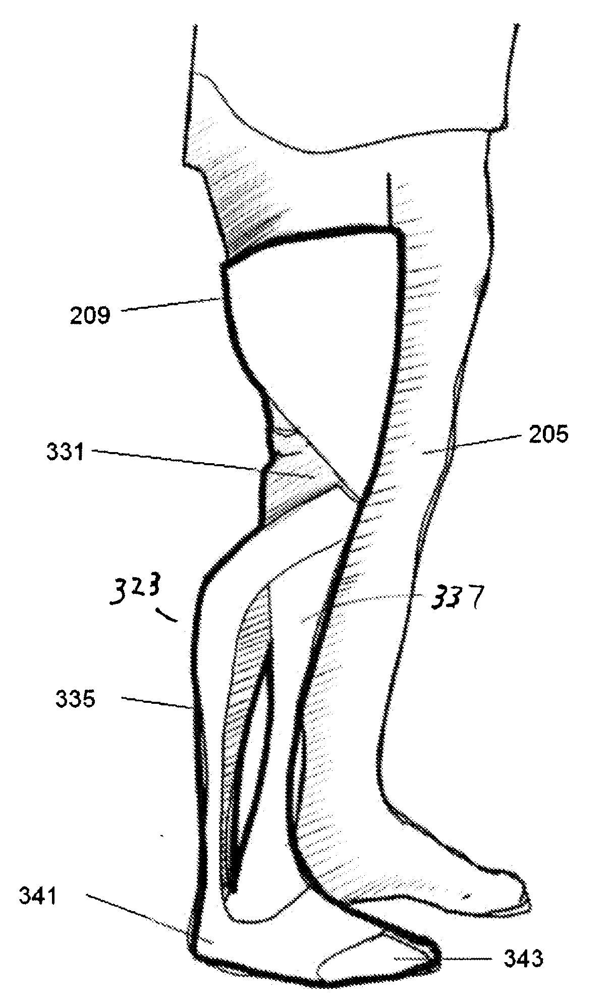
[0036]In an embodiment, the inventive prosthetic leg includes a load bearing component that functions as the human femur, knee, tibia and foot. The upper leg of the load bearing component is attached to a socket that engages the end of the amputated limb. The lower end of the upper leg and the upper end of the lower leg are coupled to the artificial knee. The lower end of the lower leg is coupled to an artificial foot. The mechanical data for the prosthetic leg may include the relative positions of the socket, knee and foot as well as the movement of these components based upon geometry and movement of the inta...


PUM


Abstract

A prosthetic limb has an outer surface that is a mirror image of an intact limb or a generic limb design. The intact limb is scanned and the surface data is manipulated to create a virtual mirror image. If generic data is used, the intact leg can be measured and the generic surface can be adjusted so the prosthetic limb appears similar to the intact limb. The end of the amputated limb is also measured to obtain socket data. A knee and foot are incorporated to form a virtual prosthetic limb represented by design data. The design data for the virtual prosthetic limb is forwarded to a rapid prototyping machine that fabricates the entire leg simultaneously. Once completed, the prosthetic limb is shipped to the patient.

Description

BACKGROUND[0001]A prosthesis limb replaces a missing extremity, such as an arm or a leg and may be needed for a variety of reasons, including diseases, and accidents. An artificial limb may also be needed when a person is born with a missing or damaged limb(s). The type of prosthesis limb used is determined largely by the extent of an amputation or loss and location of the missing limb. A transtibial prosthesis is an artificial leg that is attached to a user below the knee and includes a lower leg, ankle and foot. The transfemoral prosthesis is an artificial leg that is attached to the user's amputated limb above the knee and includes an upper leg and mechanical knee. A transradial prosthesis is an artificial arm that is attached to the user below the elbow and includes a forearm and hand. A transhumeral prosthesis is an artificial arm that is attached to the user above the elbow.[0002]In developing areas of the world, including large portions of Africa, the leading causes of amputa...

Claims


Application Information

Patent Timeline
Patent Type & Authority Applications(United States)
IPC IPC(8): A61F2/74A61F2/66A61F2/62
CPCA61F2/5046A61F2/7812A61F2/64A61F2/644A61F2/6607A61F2/80A61F2002/30426A61F2002/5043A61F2002/5047A61F2002/5049A61F2002/505A61F2002/5056A61F2002/5069A61F2002/507A61F2002/5079A61F2002/509A61F2002/5098A61F2002/607A61F2002/608A61F2002/6614A61F2002/6621A61F2002/6854A61F2220/0025A61F2/66A61F2/60B33Y80/00
Inventor SUMMIT, SCOTT
Owner 3D SYST INC
Why Eureka
Try Eureka