Recovery of energy in a hybrid vehicle having a hydraulic or pneumatic braking system

a hybrid vehicle and braking system technology, applied in the direction of engine-driven generators, braking components, process and machine control, etc., can solve the problems of generating drag torque, contributing to the deceleration of the vehicle, and the maximum electrical power generated by the generator is usually not able to be fully utilized, so as to reduce the braking pressure appropriately and reduce the braking pressure of the driver

Inactive Publication Date: 2009-12-03
ROBERT BOSCH GMBH
View PDF8 Cites 15 Cited by
  • Summary
  • Abstract
  • Description
  • Claims
  • Application Information

AI Technical Summary

Benefits of technology

[0007]In accordance with the present invention, it is provided to record the driver's braking command (the desired overall deceleration), to ascertain the vehicle deceleration that is able to be effected by the electric machine, preferably taking into account the energetic vehicle electrical system state, and to reduce appropriately the braking pressure exerted by the driver as a function of the proportion of the deceleration of the electrical machine, so that the deceleration desired by the driver is carried out. To do this, the driver's braking pressure is reduced correspondingly, using a suitable actuator (pressure reduction unit), or, if necessary, is completely removed. This has the essential advantage that the electric machine is able to be operated in a range of maximum generation of electric energy during a braking process, and consequently a maximum proportion of the kinetic energy of the vehicle may be recovered.

Problems solved by technology

The generator generates a drag torque in the process, which contributes to the deceleration of the vehicle.
This has the substantial disadvantage that the maximum electrical power that is able to be generated by the generator is usually not able to be utilized fully.

Method used


Image

  • Recovery of energy in a hybrid vehicle having a hydraulic or pneumatic braking system
  • Recovery of energy in a hybrid vehicle having a hydraulic or pneumatic braking system
  • Recovery of energy in a hybrid vehicle having a hydraulic or pneumatic braking system

Examples


Embodiment Construction

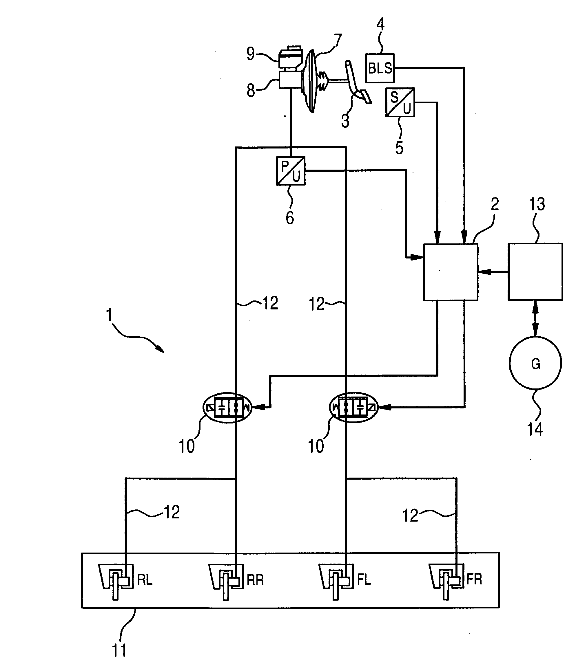
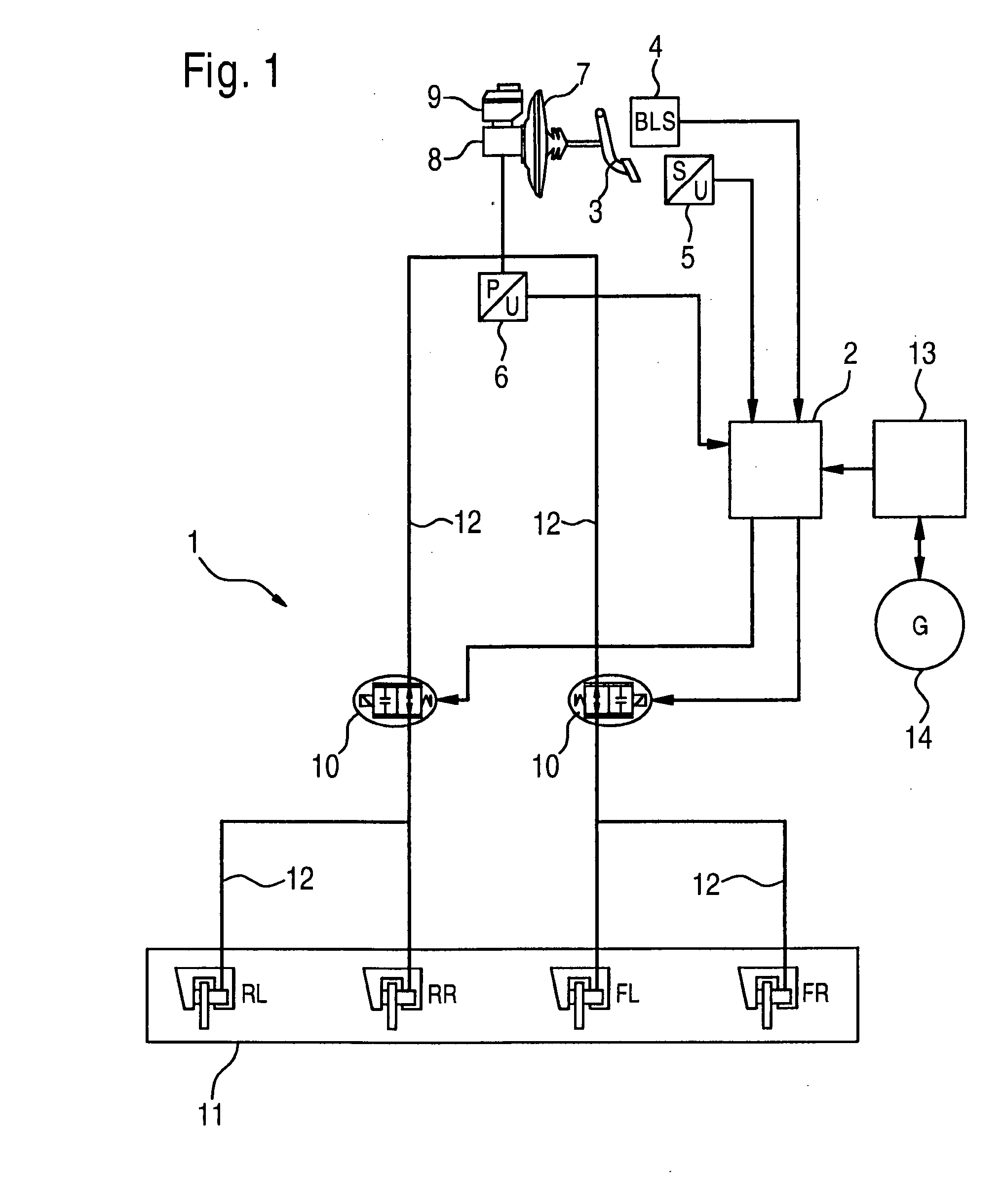
[0021]FIG. 1 shows a hydraulic motor vehicle braking system in ∥-circuit subdivision whose constructive design is essentially known from the related art. In a known way, braking system 1 includes a foot brake pedal 3, a brake booster 7 having a main brake cylinder 8 on which a brake-fluid reservoir 9 is situated. Brake booster 7 boosts the braking force exerted by the driver on foot brake pedal 3, and generates a braking pressure which is guided to wheel brakes 11 via brake lines 12.

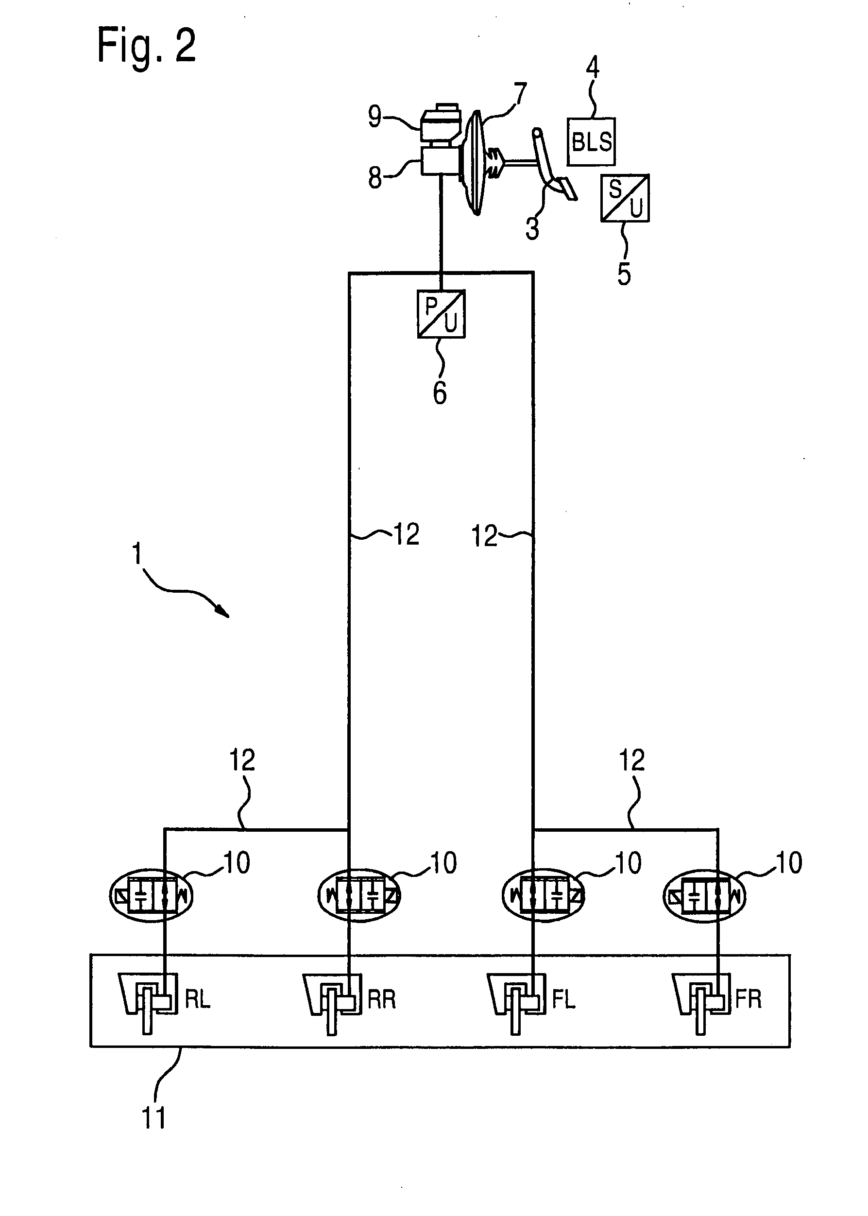
[0022]By contrast to the known braking systems, this braking system of the present invention includes an additional valve 10 which is situated in the main brake line 12 of the driven axle and is used to reduce the braking pressure exerted by the driver. (In this illustration, two valves 10 are shown, in the case of a rear-wheel drive, only left valve 10 being installed, in the case of a front-wheel drive, only right valve 10 being installed and in the case of an all-wheel drive, both valves 10 being inst...


PUM


Abstract

In a method for recovering energy in a braking process of a hybrid vehicle which has an internal combustion engine and an electric drive, as well as a hydraulic or pneumatic braking system, the exploitation of the electric drive is able to be optimized if the braking system includes at least one pressure reduction valve, using which the braking pressure exerted by the driver is able to be reduced as a function of the deceleration proportion of the electric machine.

Description

BACKGROUND OF THE INVENTION[0001]1. Field of the Invention[0002]The present invention relates to a method and a device for recovering energy in a braking process of a hybrid vehicle.[0003]2. Description of Related Art[0004]In hybrid vehicles the kinetic energy being liberated in response to a deceleration process is usually converted into electrical energy, and stored in the vehicle electrical system. Known recovery systems use the electric drive as generator for this purpose. The generator generates a drag torque in the process, which contributes to the deceleration of the vehicle. The electrical energy thus acquired may be utilized in other driving situations, either for driving the vehicle or for supplying electrical users. The efficiency of the vehicle is able to be considerably improved thereby.[0005]Known recovery systems are designed in such a way that the greatest proportion of the vehicle deceleration is effected by the service brake, and only a small proportion (depending ...

Claims


Application Information

Patent Timeline
Patent Type & Authority Applications(United States)
IPC IPC(8): G06F19/00B60T8/64B60K6/48B60L50/16B60W10/18B60W30/18
CPCB60K6/48B60T1/10B60T8/4275B60T2270/613Y02T10/92B60W10/184B60W20/00B60W30/18127Y02T10/6221B60W10/08B60L7/18B60L7/26Y02T10/62B60T13/58B60W20/13
Inventor BROECKEL, FRIEDHELMTOST, ANDREAS
Owner ROBERT BOSCH GMBH
Why Eureka
Try Eureka