
System for recovering the waste heat generated by an auxiliary system of a turbomachine

a technology of waste heat and auxiliary systems, which is applied in the direction of machines/engines, mechanical equipment, transportation and packaging, etc., can solve the problems of reducing the overall affecting the performance and efficiency of the power plant, and no known system that integrates the components, so as to reduce the work performed by the hrsg, increase the efficiency of the power plant, and remove waste heat

Inactive Publication Date: 2009-12-10
GENERAL ELECTRIC CO
View PDF12 Cites 36 Cited by
  • Summary
  • Abstract
  • Description
  • Claims
  • Application Information

AI Technical Summary

Benefits of technology

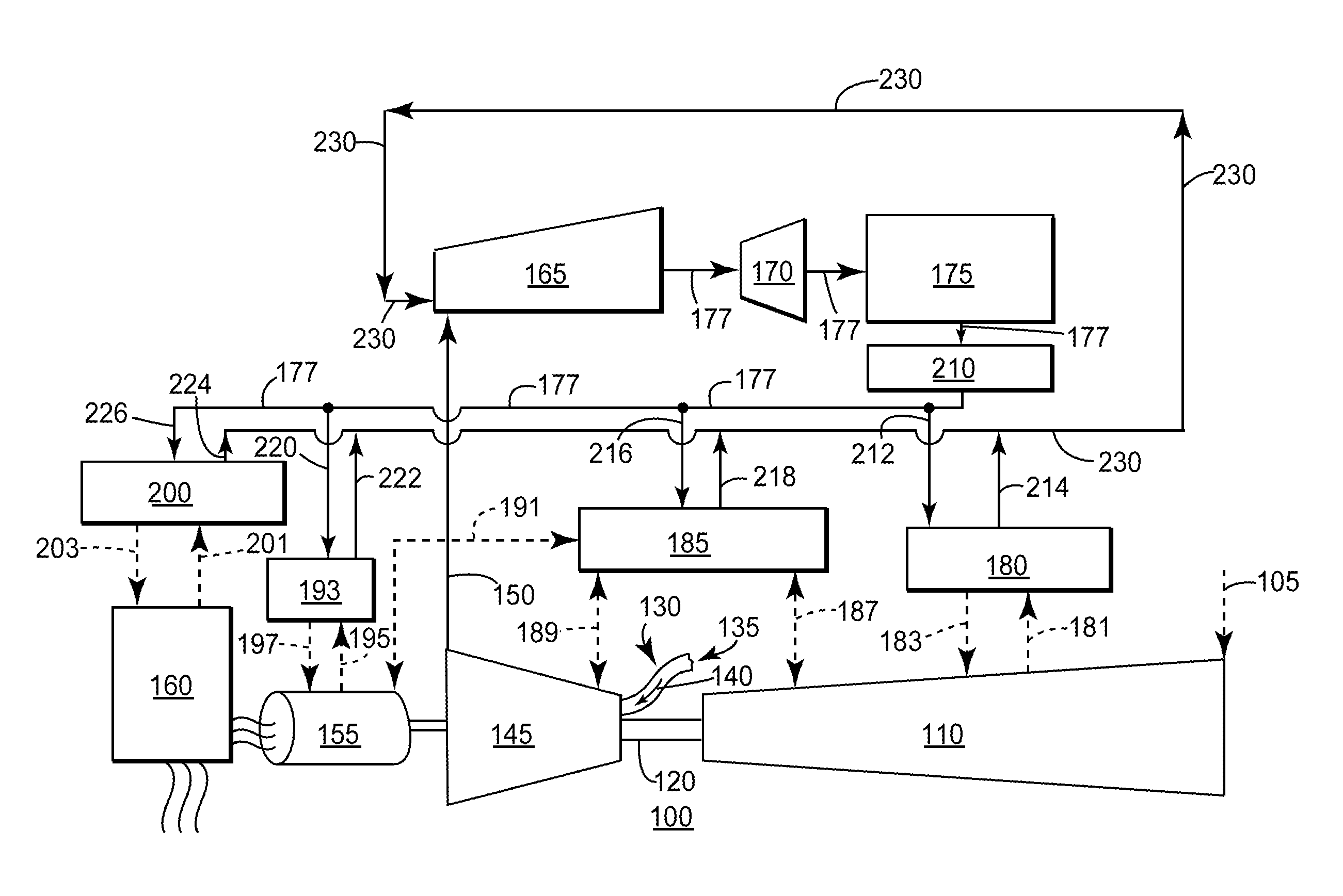
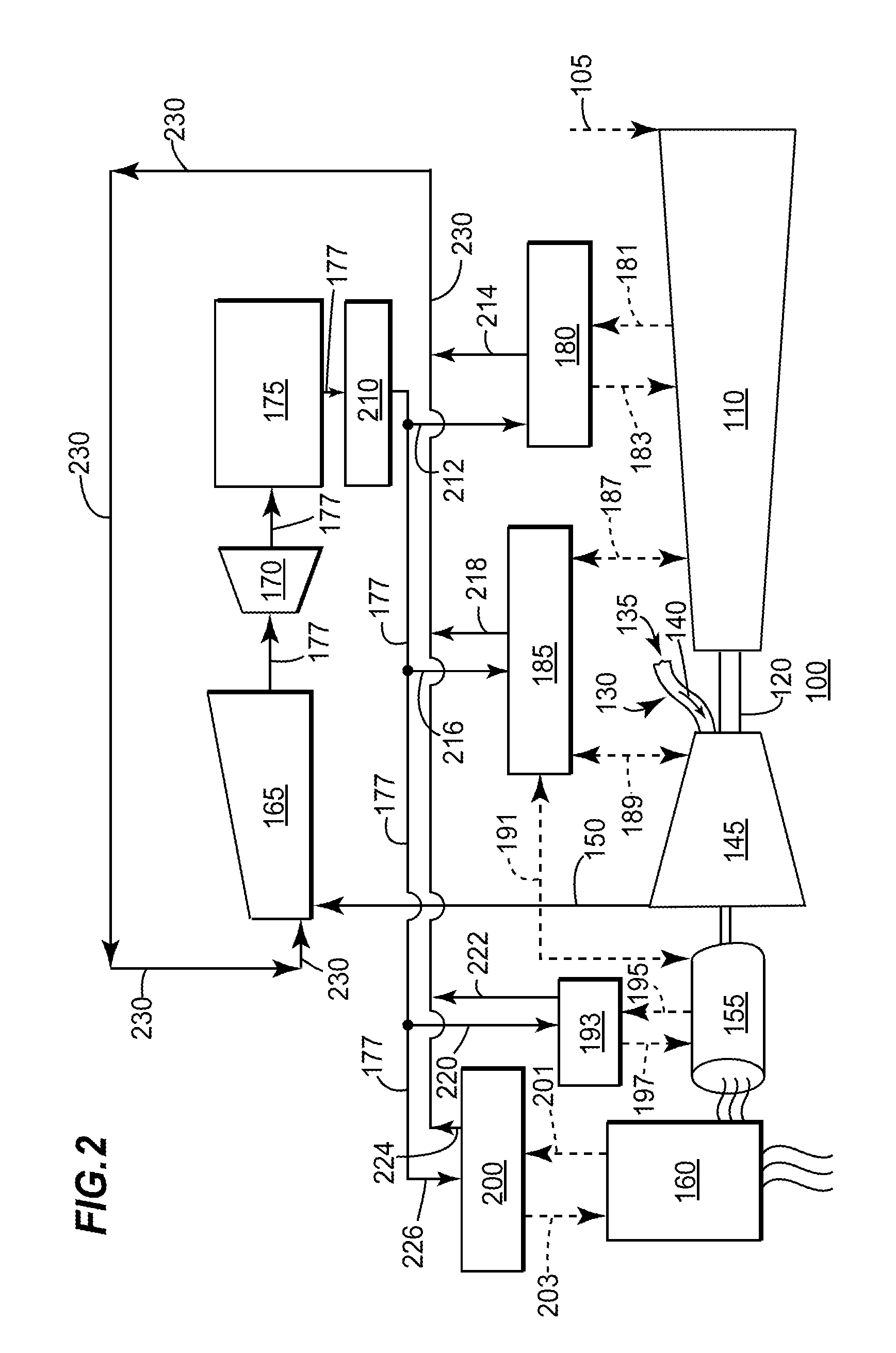
[0006]In accordance with an embodiment of the present invention, a system for increasing the efficiency of a powerplant, wherein the powerplant comprises at least one gas turbine and a heat recovery steam generator (HRSG), the system comprising: at least one auxiliary system; wherein the at least one auxiliary system is in fluid communication with at least one component of the powerplant; and removes waste heat received from the at least one component of the powerplant; a condenser integrated with the HRSG, wherein the condenser receives condensate from the HRSG and comprises a condensate loop; wherein the condensate loop transfers a portion of the condensate to an inlet portion of the at least one auxiliary system; and a heat recovery loop, wherein the heat recovery loop utilizes the condensate to transfer waste heat from the at least one auxiliary system to the HRSG; wherein the heat recovery loop increases a temperature of the condensate prior to returning to the HRSG; which reduces the work performed by the HRSG and increases the efficiency of the powerplant.
[0007]In accordance with another embodiment of the present invention, a system for integrating components of a powerplant to recapture waste heat discharged by at least one auxiliary system in fluid communication with the powerplant, the system comprising: at least one gas turbine; at least one steam turbine; at least one auxiliary system; wherein the at least one auxiliary system discharges waste heat received from at least one component of the powerplant; and is in fluid communication with the at least one component of the powerplant; a condensor integrated with the HRSG, wherein the condenser receives condensate from the HRSG and comprises a condensate loop; wherein the condensate loop transfers a portion of the condensate to an inlet portion of the at least one auxiliary system; and a heat recovery loop, wherein the heat recovery loop utilizes the condensate to transfer waste heat from the at least one auxiliary system to the HRSG; wherein the heat recovery loop increases a temperature of the condensate prior to flowing into the HRSG; which reduces the work performed by the HRSG and increases the efficiency of the powerplant.

Problems solved by technology

Generally, these cooling functions directly impact the performance and efficiency of the powerplant.
The use of the economizer in an HRSG reduces the overall efficiency of the powerplant.
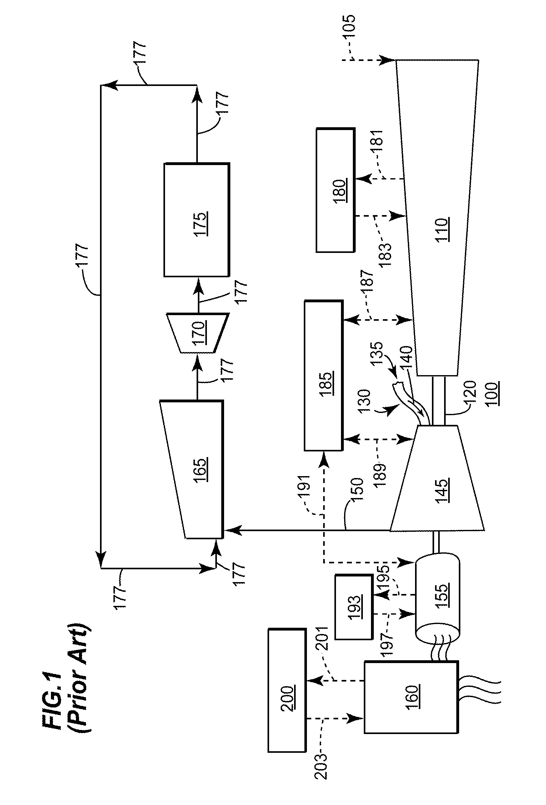
Currently, there are no known systems that integrate the components of a powerplant such that the aforementioned waste heat is used to heat the condensate and reduces economizer use is eliminated or reduced.

Method used


Image

  • System for recovering the waste heat generated by an auxiliary system of a turbomachine
  • System for recovering the waste heat generated by an auxiliary system of a turbomachine
  • System for recovering the waste heat generated by an auxiliary system of a turbomachine

Examples


Embodiment Construction

[0011]The following detailed description of preferred embodiments refers to the accompanying drawings, which illustrate specific embodiments of the invention. Other embodiments having different structures and operations do not depart from the scope of the present invention.

[0012]Certain terminology is used herein for the convenience of the reader only and is not to be taken as a limitation on the scope of the invention. For example, words such as “upper,”“lower,”“left,”“right,”“front”, “rear”“top”, “bottom”, “horizontal,”“vertical,”“upstream,”“downstream,”“fore”, “aft”, and the like; merely describe the configuration shown in the Figures. Indeed, the element or elements of an embodiment of the present invention may be oriented in any direction and the terminology, therefore, should be understood as encompassing such variations unless specified otherwise.

[0013]The present invention has the technical effect of increasing the temperature of the condensate flowing of a HRSG by integrati...


PUM


Abstract

A system increasing the efficiency of a powerplant by recovering the waste generated by an auxiliary cooling system is provided. The system may include a condensate loop and a heat recovery loop. These loops may integrate the auxiliary cooling systems of a gas turbine with the heat recovery steam generator of the powerplant. The integration may allow a smaller economizer section, which may increase the efficiency of the powerplant.

Description

BACKGROUND OF THE INVENTION[0001]The present invention relates generally to systems for increasing the efficiency of a powerplant; more specifically, but not by way of limitation, to systems for utilizing the waste heat generated by a powerplant to decrease the work performed by a heat recovery steam generator.[0002]Generally, many components and / or systems of a powerplant require cooling. These components may include for example, but not limiting of, a generator; a lube oil system; a transformer; a turbine inlet cooling system; a compressor intercooling system cooling, and the like. These components and systems reject the heat generated by inefficiencies (windage, bearings, electrical heating, etc.). Generally, these cooling functions directly impact the performance and efficiency of the powerplant.[0003]Commonly, these systems employ an individual skid that may utilize air or water-cooled heat exchangers. For example, but not limiting of. A generator cooling water skid may use a h...

Claims


Application Information

Patent Timeline
Patent Type & Authority Applications(United States)
IPC IPC(8): F02C6/18
CPCF01K23/10Y02E20/16F02C6/18F01K27/02Y02P80/15
Inventor CHILLAR, RAHUL J.SMITH, MICHAEL B.
Owner GENERAL ELECTRIC CO
Learn More