
Customized Programmable Pool Cleaner Method and Apparatus

a technology of programmable cleaning and cleaning equipment, applied in the field of robotic pool cleaners, can solve the problems of not substantially covering the bottom surface of the pool, unable to keep the cleaning on the desired path, and unable to accurately complete the turning

Inactive Publication Date: 2009-12-10
AQUATRON
View PDF7 Cites 95 Cited by
  • Summary
  • Abstract
  • Description
  • Claims
  • Application Information

AI Technical Summary

Benefits of technology

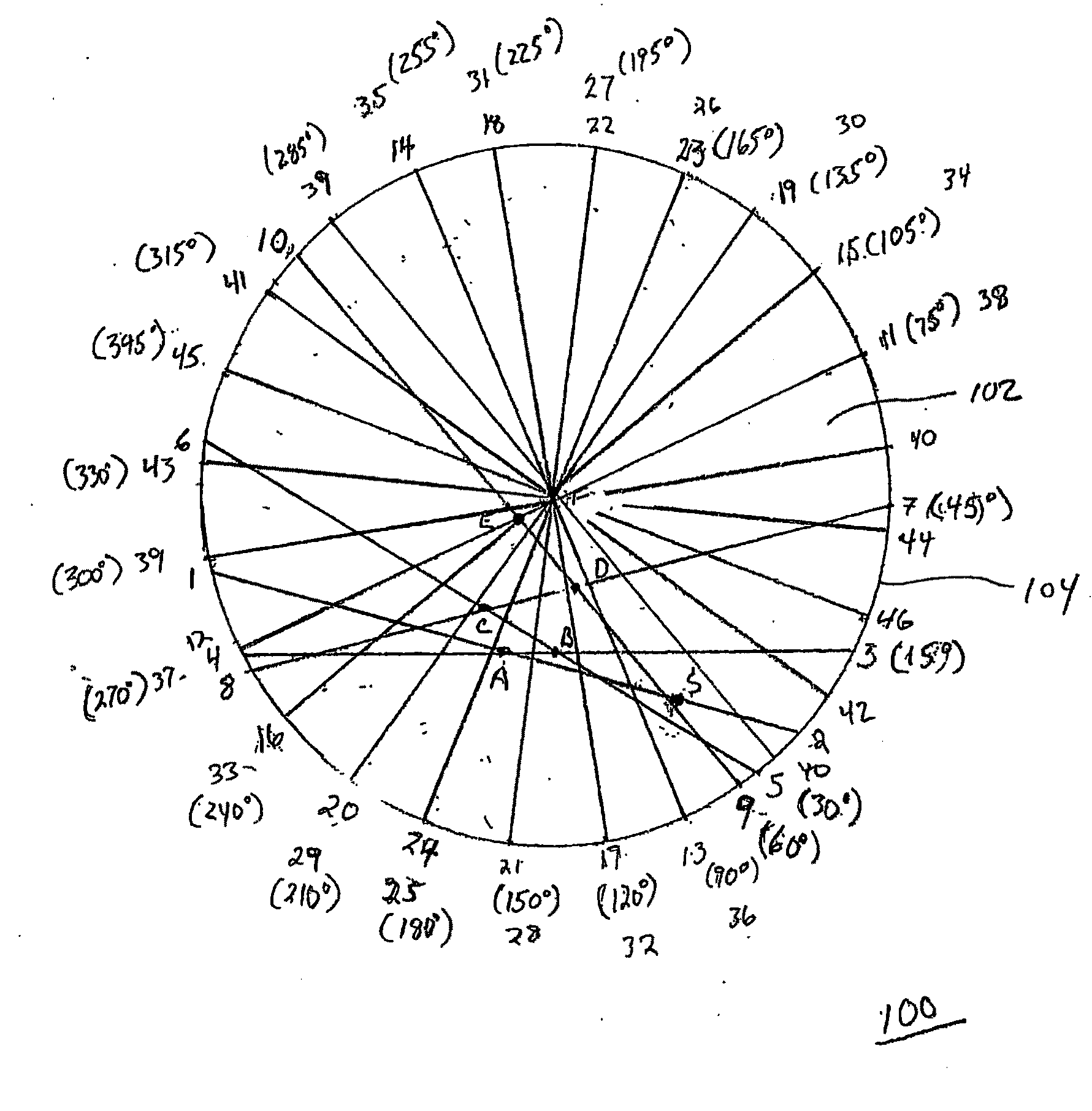
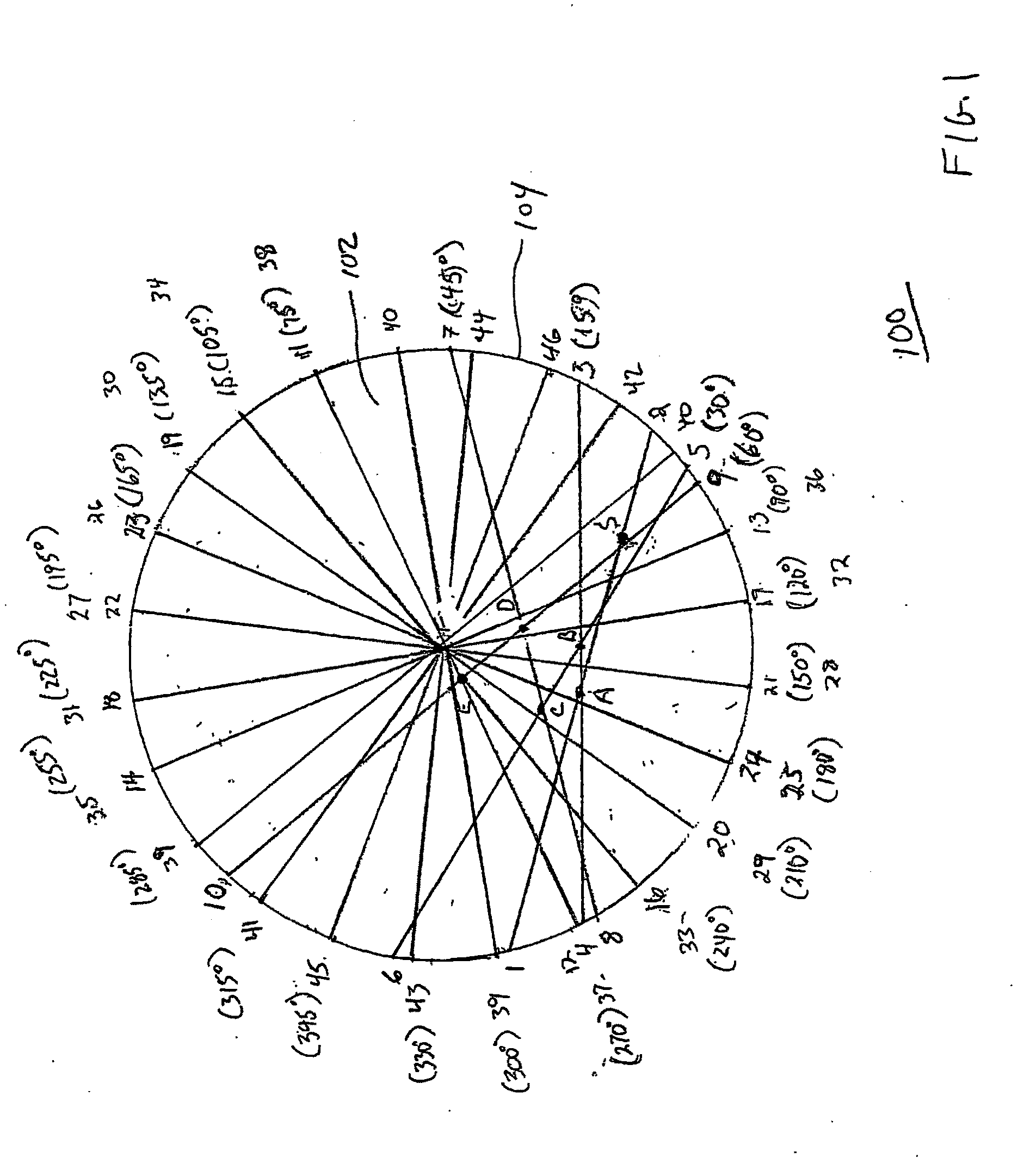
[0023]For example, a predetermined angle of turning (i.e., a turn angle) can be set for 15 degrees for a circular pool, which will generate approximately twenty-four paths to clean the entire pool. Preferably, the robot alternates between turning clockwise and counter-clockwise when a power cable extends from the robot to an external power source. Alternating the turning directions eliminates or minimizes twisting of the power cable which can interfere with the programmed movement of the pool cleaner.
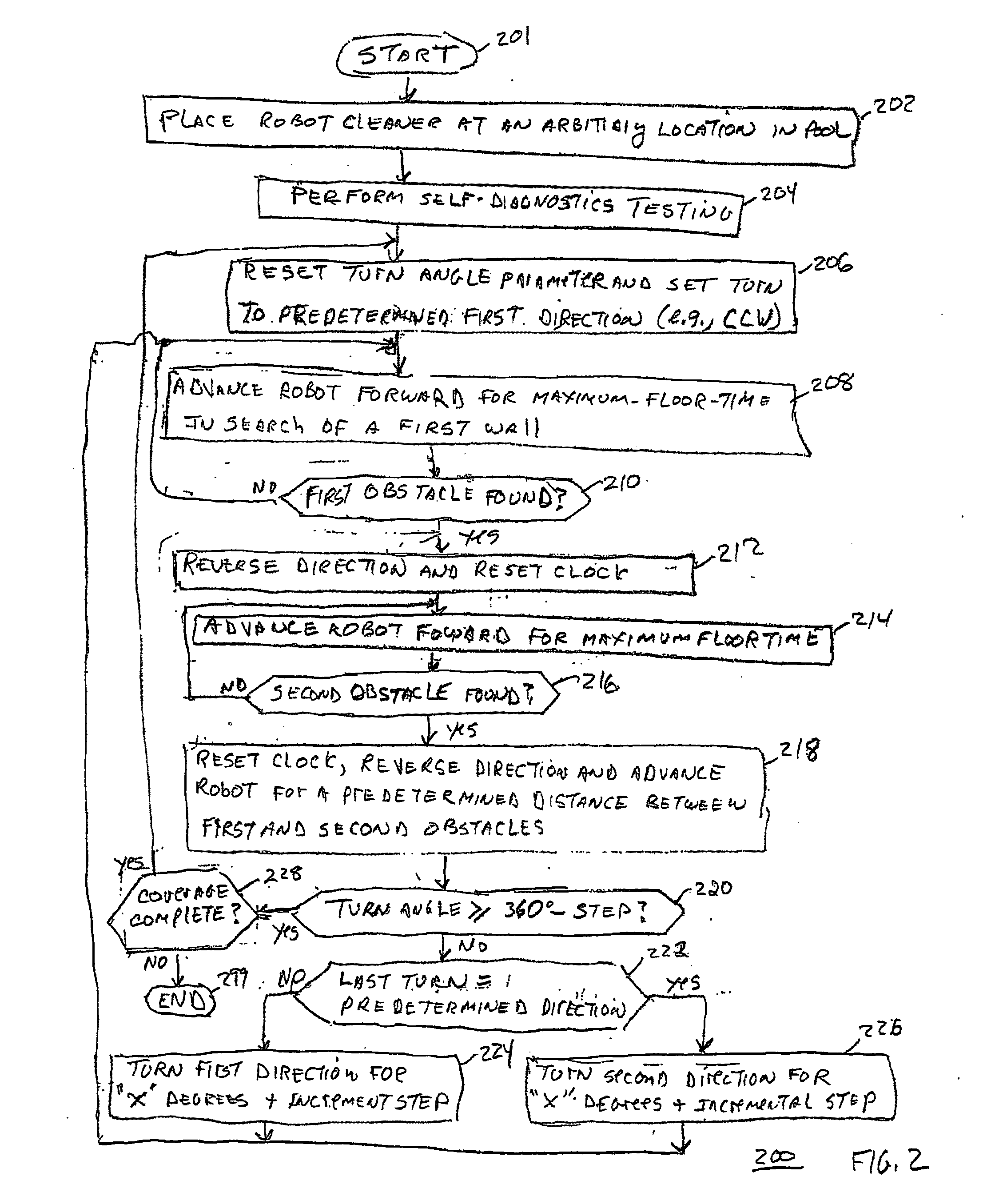
[0025]In particular, upon reaching the second obstacle, the robot will climb along the nearest wall and clean to the waterline for a predetermined time (e.g., thirty seconds), and then turn in a new direction and proceed down the wall to another point along the bottom of the pool. The robot cleaner is capable of sensing its horizontal and vertical orientations, illustratively, by a mercury switch. Once the robot is positioned substantially horizontal along the bottom of the pool, the microprocessor resets to start the scanning algorithm process over again. In this manner, the robot is able to clean this narrow area, as well as the remaining portion of the pool from a different direction.

Problems solved by technology

Contributing to the complexity of the navigational problem is the fact that even though a robot is generally programmed to travel in straight lines from side to side and make accurate turns, it is difficult to keep it on the desired path and to complete the turns accurately.
An analysis of some prior art algorithms for controlling the programmed movement of robotic cleaners indicates that they are inadequate and fail to substantially cover the pool's bottom surface.

Method used


Image

  • Customized Programmable Pool Cleaner Method and Apparatus
  • Customized Programmable Pool Cleaner Method and Apparatus
  • Customized Programmable Pool Cleaner Method and Apparatus

Examples


Embodiment Construction

[0039]An important aspect of the present invention is a novel navigationed algorithm that is used in conjunction with a pool cleaner that introduces a systematic coverage of the submerged surfaces of the pool in a predetermined pattern. The present invention includes an algorithm that is programmed into, and executed by the controller of the cleaning robot to provide a novel cleaning routine. The algorithm provides a fast and efficient pattern of movement for cleaning a bottom surface, as well as the sidewalls of a swimming pool, spa, hot tub, recreational pond, or any other recreational aquatic structure that retains a volume of water and requires cleaning. By efficient, it is meant that the pool cleaner can traverse the bottom surface of the pool to clean all, or substantially all of the surface in a relatively short period of time.

[0040]One novel feature of the present invention is that the robot can efficiently clean a pool having either a conventional or an irregular shape. Tha...


PUM


Abstract

A method and apparatus for cleaning the surfaces of a pool by a programmed robotic pool cleaner initially set at an arbitrary position in the poll. The pool can be of any standard or non-standard shapes, and the surfaced with any conventional materials. The robot is advanced until it encounters a first obstacle (1), then reverses direction and advances along the same path to an opposing second obstacle (2) to form a first path between the opposing first (1) and second (2) obstacles. At the second obstacle (2), the robot reverses and advances to a predetermined point (A) between the opposing obstacles along said first path. At the predetermined point (A), the robot stops and turns in a first direction at a predetermined angle of turn, and repeats the above steps along additional paths until the sum of the predetermined angle of turns generates a quantity of paths sufficient to substantially clean the pool surfaces.

Description

CROSS REFERENCE TO RELATED APPLICATION[0001]This patent application claims the benefit of U.S. Provisional Application Ser. No. 60 / 728,248, filed Oct. 18, 2005, the contents of which are incorporated by reference herein.FIELD OF THE INVENTION[0002]The present invention relates to robotic pool cleaners and more specifically to apparatus and methods for the programmed operation of pool cleaners for the efficient cleaning of a pool.BACKGROUND OF THE INVENTION[0003]Automatic or robotic pool cleaners available having various navigational capabilities and methods for cleaning the bottom and side walls of a pool are disclosed in the art. For example, U.S. Pat. No. 6,125,492 (Prowse), entitled Automatic Swimming Pool Cleaning Device, discloses an automatic swimming pool cleaner which includes a flexible cleaning member designed to contact an underwater surface of the swimming pool. A tube is coupled to the cleaning member for connecting the cleaning device to a water vacuum hose via a hose ...

Claims


Application Information

Patent Timeline
IPC IPC(8): B08B7/04
CPCE04H4/1654
Inventor ABEHASERA, BENPORAT, OMRY
Owner AQUATRON
Learn More