
IC having voltage regulated integrated faraday shield

a faraday shield and voltage regulation technology, applied in the field of electronic systems, can solve the problems of reducing the performance of the underlying rf circuitry, time-consuming retuning process, and high cost of implementation

Active Publication Date: 2009-12-10
TEXAS INSTR INC
View PDF4 Cites 49 Cited by
  • Summary
  • Abstract
  • Description
  • Claims
  • Application Information

AI Technical Summary

Benefits of technology

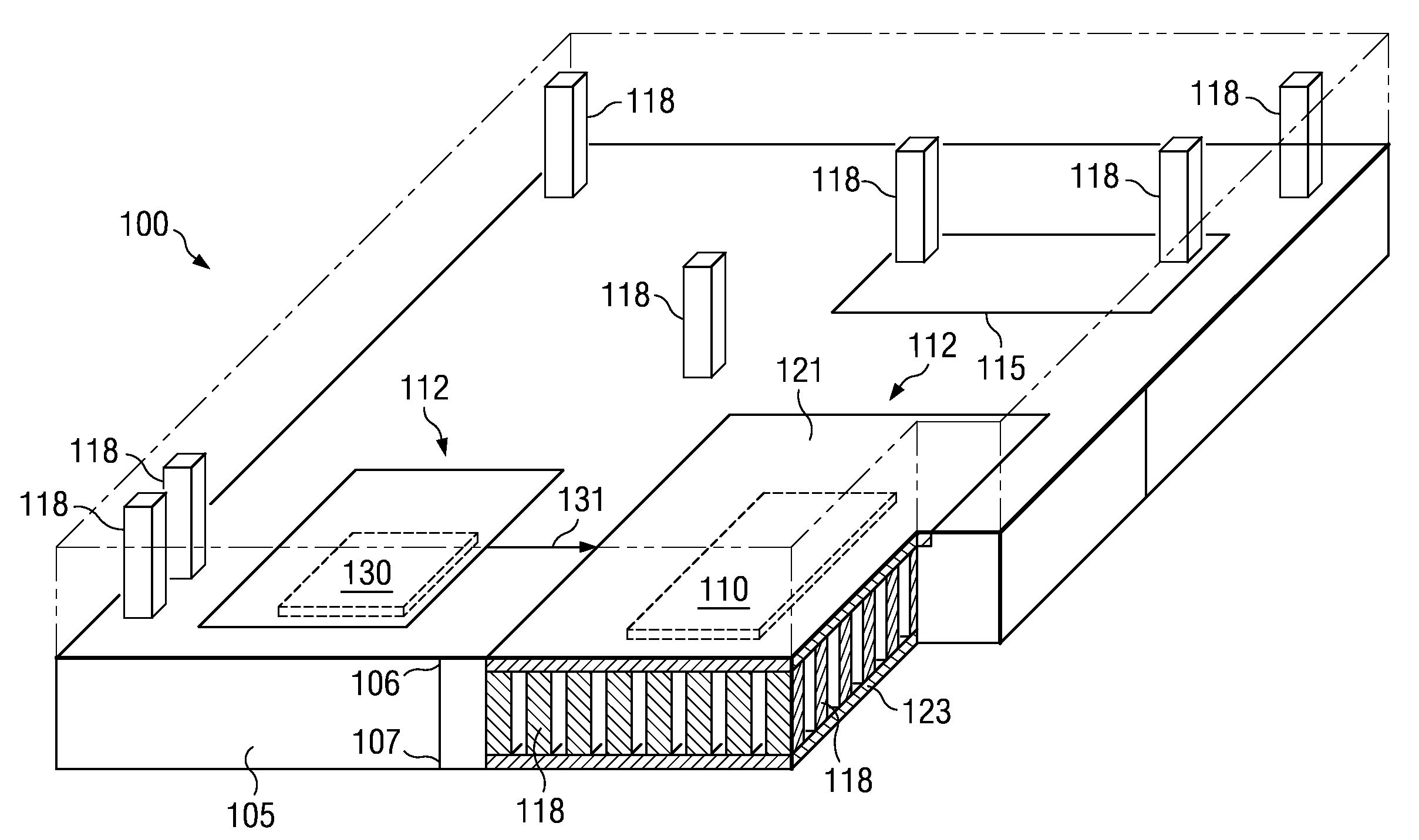
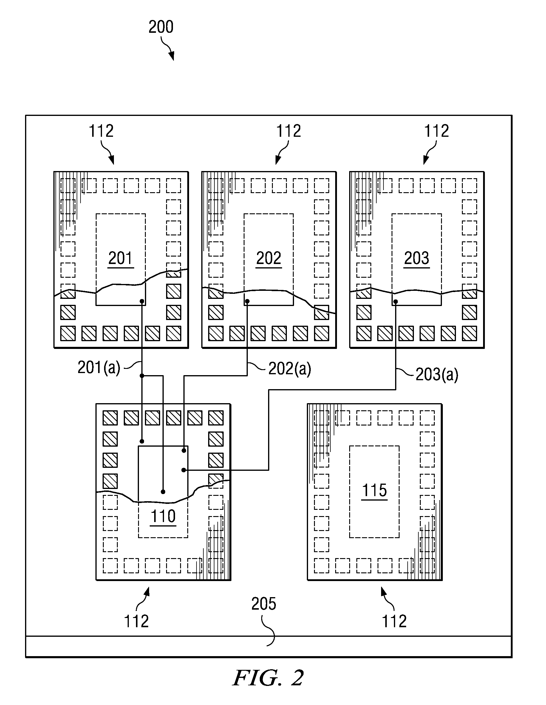
[0011]In some embodiments of the invention, a voltage regulator that provides a regulated “clean” power supply rail is generally coupled to clamp the potential on the integrated Faraday shield. The voltage regulator can be formed on the same IC with the active circuitry, such as within the same integrated Faraday shield, or on top or below the IC having the active circuitry and integrated Faraday shield. The voltage regulator can itself include an integrated Faraday shield. In another embodiment of the invention, more than one voltage regulator is provided, which can provide a plurality of clean different voltage levels for the IC.

Problems solved by technology

However, this implementation is costly and time consuming, as the metal cans used for RF shielding must be customized according to individual circuit boards.
Additionally, metal cans being external shields increase the space requirements for RF sections and, more significantly, can degrade the performance of the underlying RF circuitry, such as by itself acting as a broadcast antenna of RF noise.
This performance degradation generally leads to a time-consuming retuning process that may be necessary to limit the effects of the metal can.
Moreover, although metal cans can significantly reduce radiated EMI including radiated RFI, metal cans do not provide protection from EMI coupled through a common monolithic IC substrate (e.g., bulk silicon) referred to herein as “substrate coupling,” as described below.
As with metal cans, a limitation of package-level plating is the inability to provide protection from substrate coupling.
Substrate coupling can be a significant problem particularly for monolithic mixed signal RF comprising ICs.
Generally, in mixed signal systems, such substrate noise can corrupt the sensitive low level analog circuitry (e.g., RF subcircuits) and thus impair the performance of the mixed signal IC.

Method used


Image

  • IC having voltage regulated integrated faraday shield
  • IC having voltage regulated integrated faraday shield
  • IC having voltage regulated integrated faraday shield

Examples


Embodiment Construction

[0016]Embodiments of the invention are described with reference to the attached figures, wherein like reference numerals are used throughout the figures to designate similar or equivalent elements. The figures are not drawn to scale and they are provided merely to illustrate the instant invention. Several aspects of the invention are described below with reference to example applications for illustration. It should be understood that numerous specific details, relationships, and methods are set forth to provide a full understanding of the invention. One having ordinary skill in the relevant art, however, will readily recognize that the invention can be practiced without one or more of the specific details or with other methods. In other instances, well-known structures or operations are not shown in detail to avoid obscuring the invention. Embodiments of the invention are not limited by the illustrated ordering of acts or events, as some acts may occur in different orders and / or con...


PUM


Abstract

An integrated circuit (IC) includes a substrate having a top semiconductor surface and a bottom surface, and integrated circuitry including an analog subcircuit and at least one digital subcircuit formed on the top semiconductor surface. A plurality of through substrate vias (TSVs) extend through the substrate. At least one integrated Faraday shield includes a top and a bottom electrically conducting member that are coupled by the TSVs which surround the analog subcircuit and / or the digital subcircuit. At least one voltage regulator supplies a regulated power supply voltage that is coupled to the integrated Faraday shield that surrounds the analog subcircuit.

Description

CROSS REFERENCE TO RELATED APPLICATIONS[0001]This application claims the benefit of Provisional Application Ser. No. 61 / 059,426 entitled “TSV ENABLED INTEGRATED AND REGULATED RF SHIELDING”, filed Jun. 6, 2008, which is herein incorporated by reference in its entirety.FIELD OF THE INVENTION[0002]Embodiments of the invention relate to electronic systems comprising integrated circuits (ICs) and Faraday shielding for reducing electromagnetic interference (EMI) to or from the IC(s).BACKGROUND[0003]EMI is generally defined to include all potential sources of interference (i.e. unwanted disturbances, or noise) that can compromise the performance of electrical circuits due to electromagnetic coupling including RF interference. EMI is known to propagate in the solid state through conduction over signal and power lines and through the substrate, and also over the air as electromagnetic radiation in free space. For example, RF receivers are known to need good noise immunity for reception of lo...

Claims


Application Information

Patent Timeline
IPC IPC(8): H01L23/58
CPCH01L23/481H01L23/552H01L2224/16H01L25/16H01L2225/06513H01L25/0657H01L24/05H01L2224/05009H01L2224/05147H01L2224/05184H01L2224/05568H01L2224/05573H01L2924/00014H01L2224/05599
Inventor CHAUHAN, SATYENDRA SINGHHOWARD, GREGORY E.
Owner TEXAS INSTR INC
Learn More