
Hood impact absorbing apparatus

a technology of impact absorption and hood, which is applied in the direction of roofs, pedestrian/occupant safety arrangements, tractors, etc., can solve the problem of not being able to sufficiently mitigate the impact to the collision body, and achieve the effect of reducing the number of components, and reducing the number of impacts

Active Publication Date: 2009-12-10
TOYOTA JIDOSHA KK +1
View PDF3 Cites 26 Cited by
  • Summary
  • Abstract
  • Description
  • Claims
  • Application Information

AI Technical Summary

Benefits of technology

The present invention provides a hood impact absorbing apparatus that can further mitigate the impact that a collision body receives from a hood. Compared to conventional art, the invention allows for a larger deformation of the push-up rod during a collision, resulting in a gradual decrease in the speed of the collision. This is achieved by modifying the push-up rod's path of movement and the angle at which it contacts the slide surface. The invention also provides multiple peaks of frictional force to further reduce the impact energy absorbed by the collision body.

Problems solved by technology

This makes it impossible to sufficiently mitigate the impact to the collision body.

Method used


Image

  • Hood impact absorbing apparatus
  • Hood impact absorbing apparatus
  • Hood impact absorbing apparatus

Examples


first embodiment

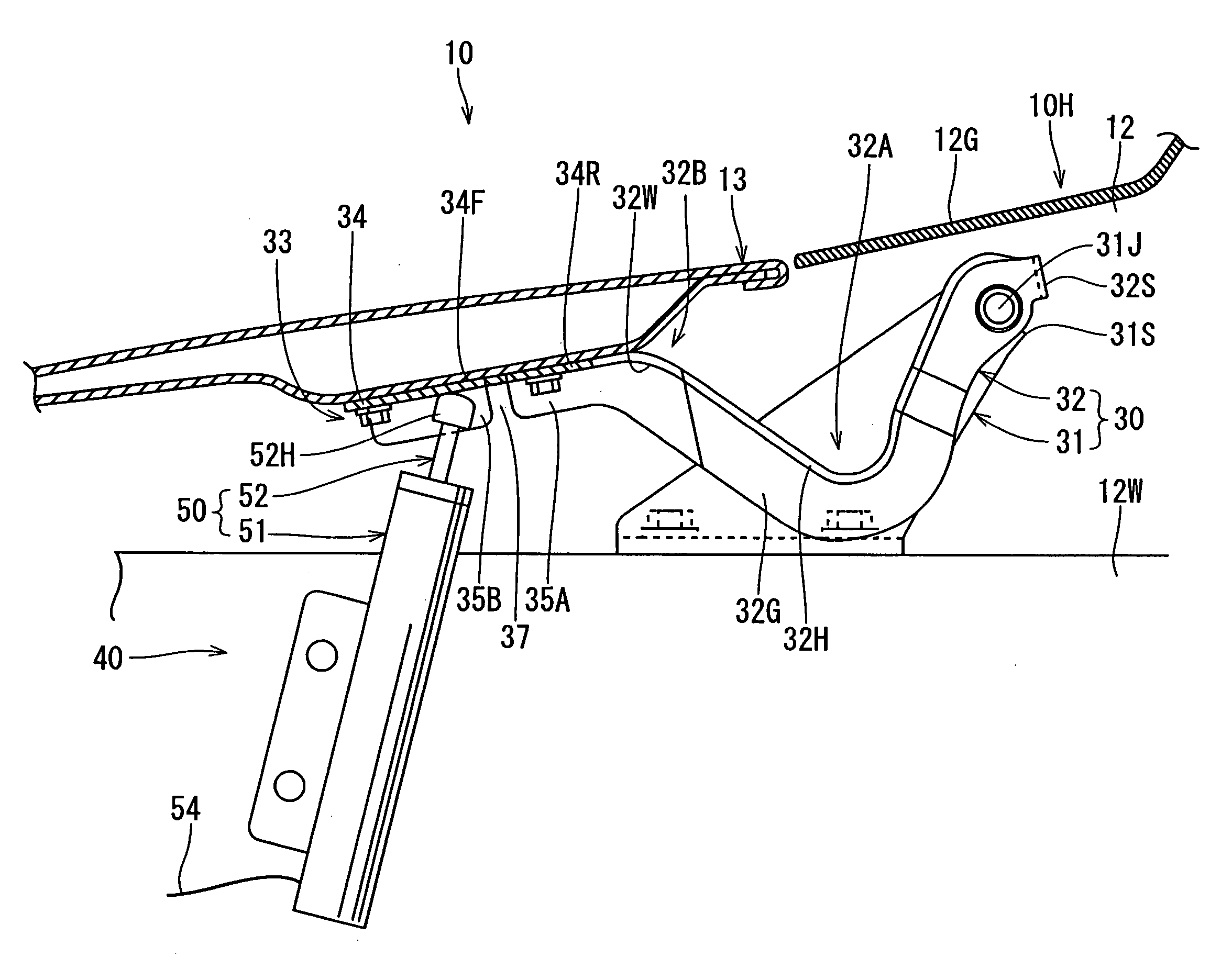
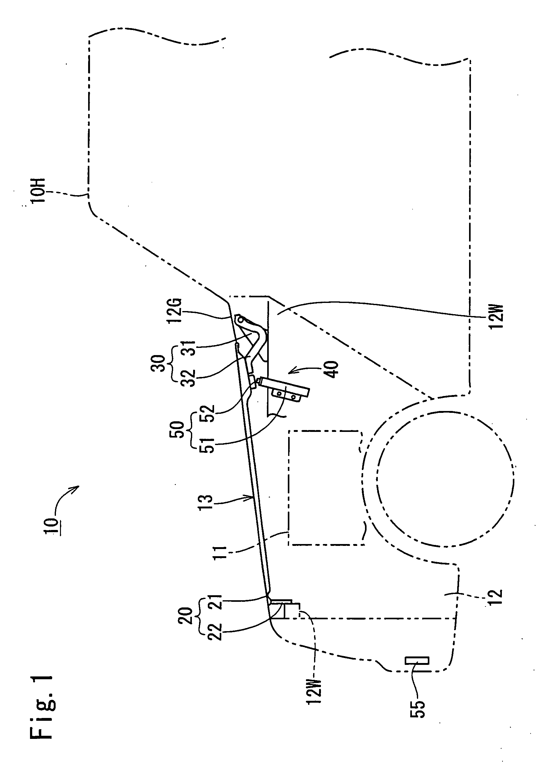
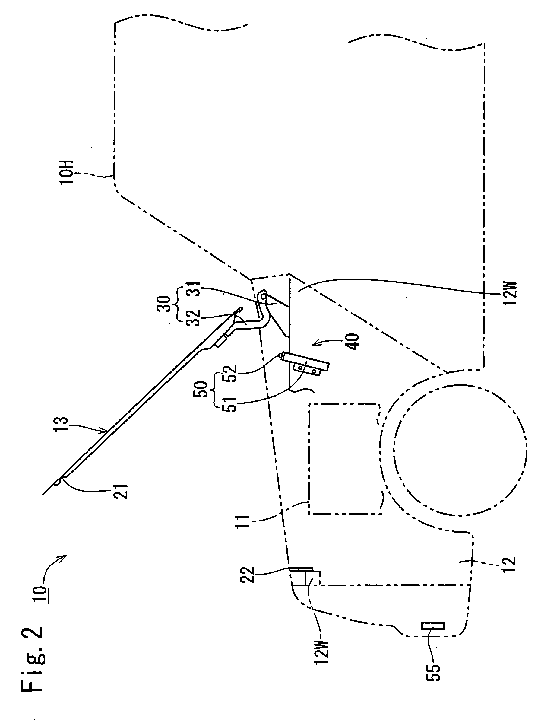
[0039]Hereinafter, the present invention will be described based on FIG. 1 to FIG. 14. A vehicle 10 shown in FIG. 1 is provided with an engine room 12 accommodating an engine 11 at the front side. The top surface of the engine room 12 is closed by a hood 13.

[0040]The rear end of the hood 13 is joined to a vehicle main body 10H by a hinge mechanism 30 while the front end of the hood 13 is joined to the vehicle main body 10H by a lock mechanism 20. The lock mechanism 20 is placed at the center in a lateral direction of the hood 13, as shown in FIG. 4, and is composed of a striker 21 arranged on the undersurface in the front end of the hood 13 and a lock device 22 incorporated in an inner wall 12W in the front end of the engine room 12, as shown in FIG. 1. The striker 21 is shaped such that around rod is curved and deformed in a portal shape. The lock device 22 includes a latch (not shown) that moves rotationally to be meshed with the striker 21 and a ratchet (not shown) that regulates...

second embodiment

[0068]The joining rib 60G of the rod slide contact member 60 is approximately the same in shape as the joint protrusion piece 32T. In the front end of the joining rib 60G, a long hole 61 extending in the back-and-forth direction is formed while in the rear end of the joining rib 60G, a round hole 62 is formed. With the long hole 61, a pin 63 protruded from the front end of the joint protrusion piece 32T is engaged in a falling-off preventive state. On the other hand, with the round hole 62, a knockout pin 64 protruded from the rear end of the joint protrusion piece 32T is fitted, as shown in FIG. 15. The configuration of the second embodiment has been described above.

[0069]According to this configuration, normally, the rod slide contact member 60 and the hinge arm 32V are fixed integrally, as shown in FIG. 15. At the time of canceling the engagement between the striker 21 (see FIG. 1) and the lock device 22 (see FIG. 1), the hood 13 and the hinge arm 32V are rotationally moved integ...


PUM


Abstract

The present invention provides a hood impact absorbing apparatus capable of further mitigating an impact that a collision body receives from a hood than ever, wherein a push-up rod pushes up the rear end of a hood at the time of a collision of a vehicle, and when a collision body is battered against the top surface of the hood in this state, the rear end of the hood descends and the distal end of the push-up rod slidingly contacts and moves a rear-side flat portion and an arm intermediate curved portion in the rear end of the hood, and herein, a slide contact angle (θ) in the arm intermediate curved portion is larger than a slide contact angle (θ) in the rear end of the rear-side flat portion, thereby, during a process in which the rear end of the hood descends, peaks at which an absorbing amount of impact energy becomes large can be provided at least twice, and as a result, the impact can be mitigated further than ever.

Description

BACKGROUND OF THE INVENTION[0001]1. Field of the Invention[0002]The present invention relates to a hood impact absorbing apparatus configured such that a rear end of a hood is pushed up at the time of a collision of a vehicle so as to allow the rear end of the hood to descend when a collision body such as a pedestrian is battered against the top surface of the hood, thereby mitigating the impact to the collision body.[0003]2. Description of the Related Art[0004]Conventionally, this type of a hood impact absorbing apparatus is configured such that a concave receiving surface is arranged on the undersurface of the rear end of a hood so as to bring a distal end of a push-up rod into contact with that surface. A side surface of the proximal end of the push-up rod is formed with a notch portion. When a collision body (e.g., a pedestrian) is battered against the top surface of the hood in a state where the push-up rod pushes up the rear end of the hood, the push-up rod is fractured at the...

Claims


Application Information

Patent Timeline
Patent Type & Authority Applications(United States)
IPC IPC(8): B60J7/00B60R21/34B60R21/38B62D25/10
CPCB60R21/38
Inventor MORI, SHINJINAKAGAWA, YUKIOYOSHIYAMA, KAZUYUKIHAYASHI, TAKEKISUZUKI, SHIGEYUKI
Owner TOYOTA JIDOSHA KK
Learn More