Motion Detection Systems Using CW Radar in Combination With Additional Sensors

a technology of motion detection and cw radar, applied in the field of cw radar, can solve the problems of inability to ensure reliable detection, inability to use cw radar sensors alone, and inability to detect moving objects, so as to improve discrimination and classification of moving objects, reduce false alarm rates, and reduce power consumption

Active Publication Date: 2009-12-10
III HLDG 1
View PDF27 Cites 205 Cited by
  • Summary
  • Abstract
  • Description
  • Claims
  • Application Information

AI Technical Summary

Benefits of technology

[0035]In summary, whether or not the CW radar is utilized for through-the-wall detection, an additional one or more sensors are used with the CW radar to confirm the motion detection result or to turn on the CW radar once motion or the physical presence of an individual has been sensed, thereby to provide confirmation of events sensed by a less-reliable sensor with the use of CW radar. Thus, the addition of other sensors provides lower power consumption, lower false alarm rates and better discrimination and classification of moving objects.

Problems solved by technology

It is well known that such sensors often have coverage limitations that make it difficult to insure reliable detection or may have false alarm rates that are unacceptable.
CW radar sensors by themselves, however, may have their own limitations such as relatively high power drain and a relatively high false alarm rate.
When these CW movement detection radars are utilized and are battery-powered, they draw a considerable amount of current.
Thus CW radar is not useful for long-term surveillance applications.
Moreover, if numbers of CW radar sensors are used to track a moving object, the combined power drain would not be compatible with long-term surveillance applications.

Method used


Image

  • Motion Detection Systems Using CW Radar in Combination With Additional Sensors
  • Motion Detection Systems Using CW Radar in Combination With Additional Sensors
  • Motion Detection Systems Using CW Radar in Combination With Additional Sensors

Examples


Embodiment Construction

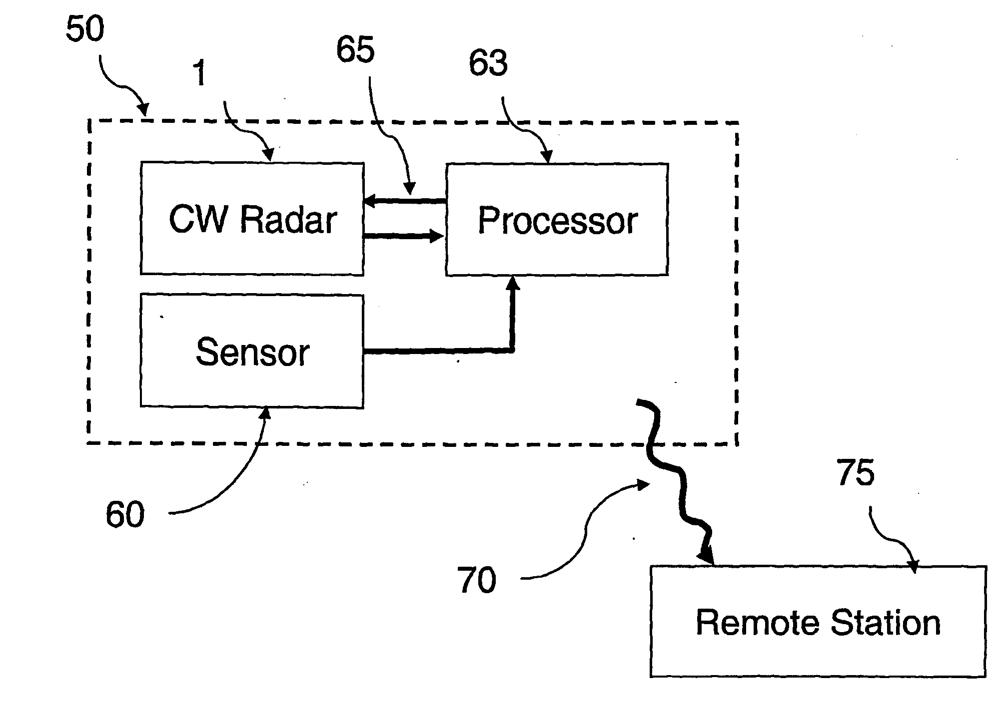
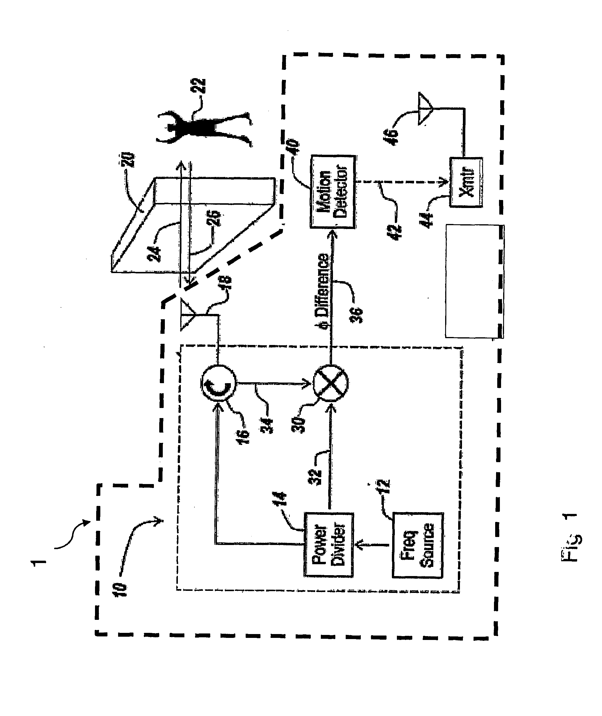
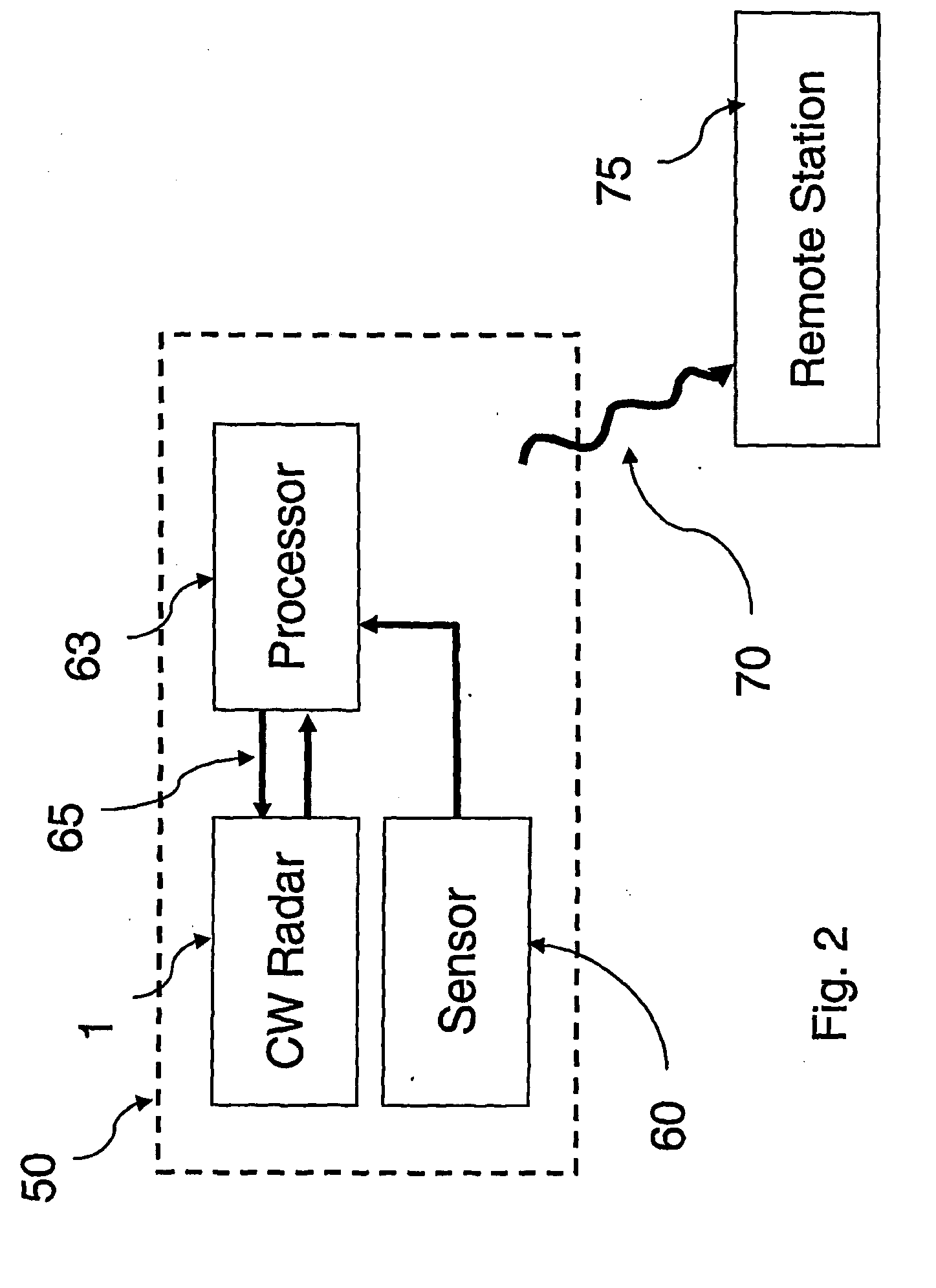
[0039]Referring now to FIG. 1, prior art motion detector 1 of the referenced application includes a CW radar 10 consisting of frequency source 12, power divider 14 circulator 16, antenna 18 and mixer 30.

[0040]In one embodiment, antenna 18 is a directional antenna such as a YAGI or flat panel, so as to project a majority of the radar energy in a given direction, to ascertain the presence of a moving object within that beam. In another embodiment, the antenna is omni-directional, so that any moving object that comes into the vicinity is detected.

[0041]In one embodiment, radar 10 is a single frequency radar with frequency source 12 set optimally to 900 MHZ.

[0042]As illustrated, one output of power divider 14 is coupled to circulator 16, which is coupled to antenna 18. The antenna forms CW beam 24, which penetrates wall 20. Signal 26, reflected from moving object 22 behind the wall, is received by antenna 18 and sent to circulator 16. Circulator 16 passes reflected signal 26 to mixer 30...


PUM


Abstract

Whether or not the CW radar is utilized for through-the-wall detection, additional one or more sensors are used with the CW radar to confirm the motion detection result or to in fact turn on the CW radar once motion or the physical presence of an individual has been sensed, thereby to provide confirmation of a less-reliable sensor with the use of the more reliable CW radar. Thus, the addition of other sensors provides lower power consumption, lower false alarm rates and better discrimination and classification of moving objects.

Description

RELATED APPLICATIONS[0001]This Application claims rights under 35 USC § 119(e) from U.S. Application Ser. No. 60 / 726,960 filed Oct. 14, 2005, the contents of which are incorporated herein by reference. This Application is related to U.S. Application US2004 / 30116 filed Sep. 14, 2004 by Paul D. Zemany, Jr. of Amherst, N.H., entitled “Method and Apparatus for Through-the-Wall Motion Detection Utilizing CW Radar;” and U.S. Application US2004 / 30116 filed Sep. 14, 2004 by Eldon M. Sutphin of Merrimack, N.H., entitled “Combined Radar and Communications Link.” The contents of these two applications are incorporated herein by reference.FIELD OF THE INVENTION[0002]This invention relates to the use of CW radar in combination with one or more additional sensors for detecting the motion of objects, animals or people.BACKGROUND OF THE INVENTION[0003]It is often desirable to detect moving objects, animals or individuals, for instance, in a security system in a building. Sensors in these security s...

Claims


Application Information

Patent Timeline
Patent Type & Authority Applications(United States)
IPC IPC(8): G01S13/56
CPCG01S7/003G01S13/888G01S13/56
Inventor ZEMANY, PAUL D.
Owner III HLDG 1
Why Eureka
Try Eureka