Three-dimensional image display apparatus

a display apparatus and three-dimensional technology, applied in the field of three-dimensional image display apparatus, can solve the problems of reducing the size of the respective projector unit, unable to achieve significant improvement in the display density of the current display apparatus, and unable to detect objects in the real world, so as to reduce the load of the image data processing system

Inactive Publication Date: 2009-12-10
SONY CORP
View PDF10 Cites 50 Cited by
  • Summary
  • Abstract
  • Description
  • Claims
  • Application Information

AI Technical Summary

Benefits of technology

[0017]Also, from the viewpoint of the load reduction of the image data system in the three-dimensional image display apparatus, a strong demand exists for a technology with which the three-dimensional image based on light rays having a quality similar to that of the object in the real world can be obtained even when the light ray group used for the three-dimensional image display is generated and scattered at a spatially lower density.
[0018]Therefore, it...

Problems solved by technology

However, the image generated by the current light ray reconstruction method lacks sense of presence as compared with the object in the real world.
However, a significant improvement in the display density in the current display apparatus is difficult due to problems in light use efficiency and diffraction limit.
In addition, in the case of the apparatus shown in FIG. 52, a limit exists in size reduction of the respective projector units 301, and it is considered that the disposal of the projector units at a spatially high density is difficult.
In either case, to generate the light ray group at the high density, a plurality of devices are to be us...

Method used


Image

  • Three-dimensional image display apparatus
  • Three-dimensional image display apparatus
  • Three-dimensional image display apparatus

Examples


embodiment 1

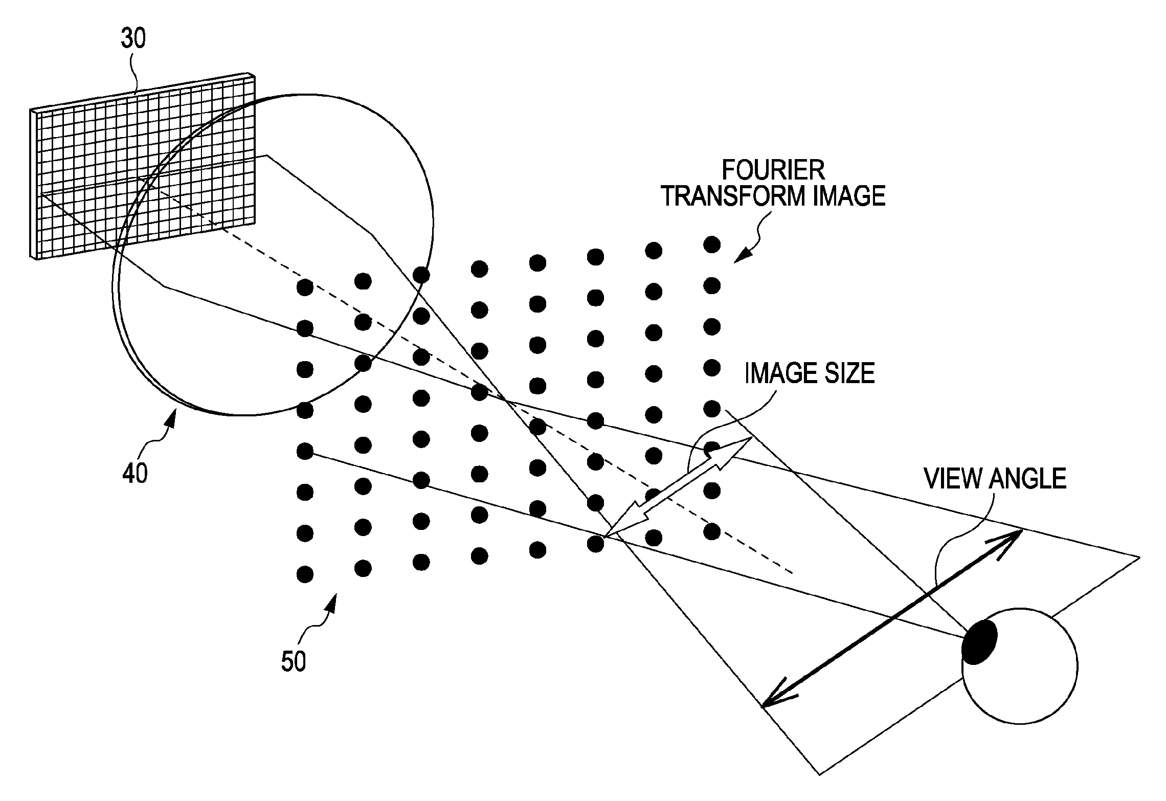
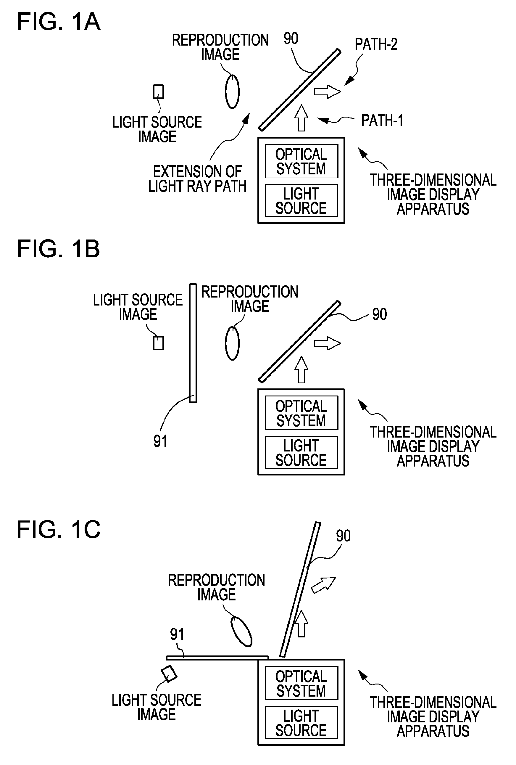
[0284]Embodiment 1 relates to a three-dimensional image display apparatus according to embodiment modes 1A and 2A. FIGS. 1A, 3, 4, and 5 are conceptual diagrams of the monochromatic-display three-dimensional image display apparatus according to Embodiment 1. It should be noted that in FIG. 3, the optical axis is set as z axis, orthogonal coordinates in a plane orthogonal to the z axis are set as x axis and y axis, a direction parallel to the x axis is set as X direction, and a direction parallel to the y axis is set as Y direction. The X direction is set, for example, as a horizontal direction in the three-dimensional image display apparatus, and the Y direction is set, for example, as a vertical direction in the three-dimensional image display apparatus. Herein, FIG. 3 is a conceptual diagram of the three-dimensional image display apparatus according to Embodiment 1 in a yz plane. A conceptual diagram of the three-dimensional image display apparatus according to Embodiment 1 in an ...

embodiment 2

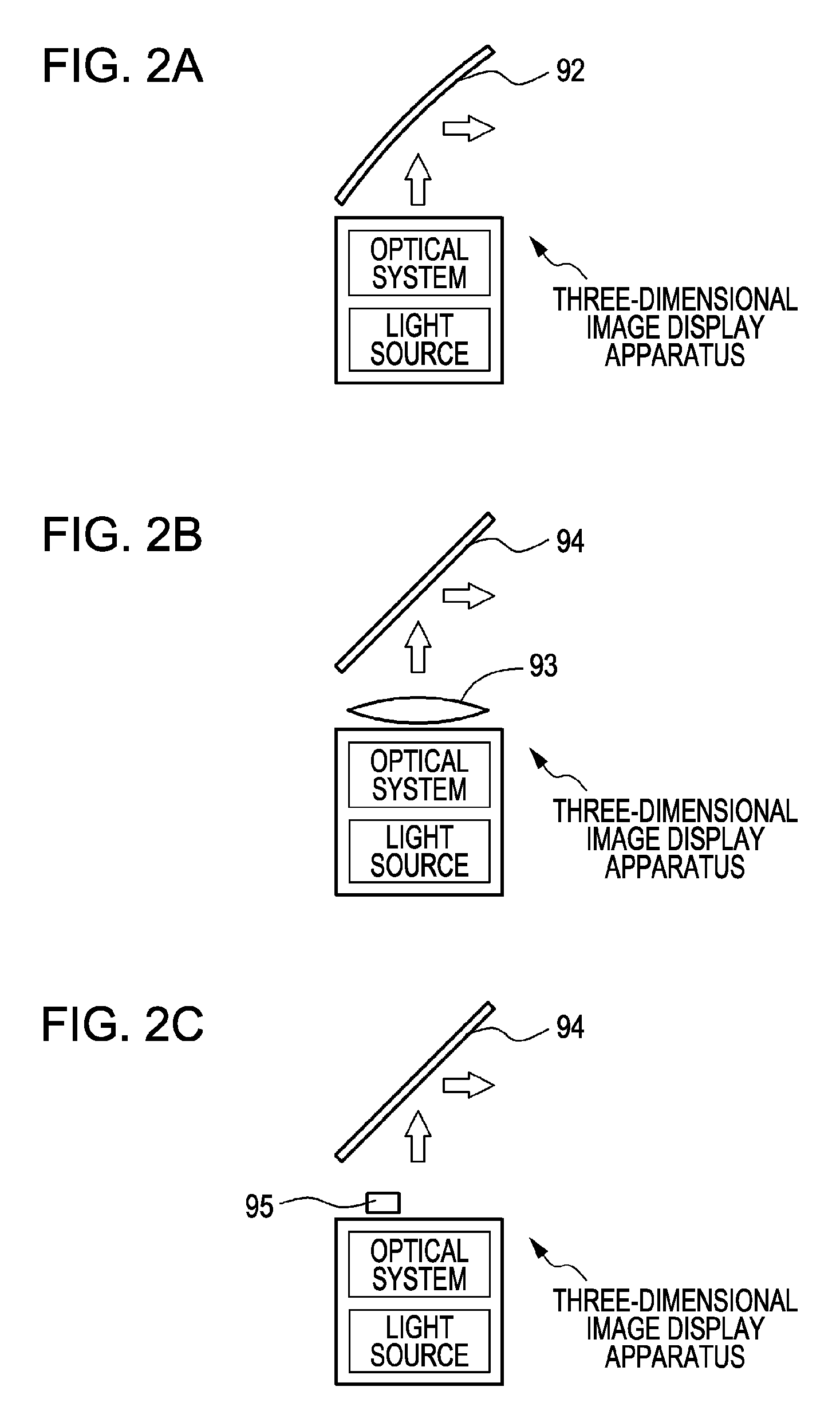
[0329]Embodiment 2 relates to a three-dimensional image display apparatus according to embodiment mode 1B and 2B. The three-dimensional image display apparatus according to Embodiment 2 is provided with light ray control means configured to change the travelling direction of the light ray emitted from the optical system and control the collecting state at the observation spot of the light rays emitted from the optical system instead of the semi-transmissive mirror configured to change the travelling direction of the light ray emitted from the optical system, which is different from the three-dimensional image display apparatus described according to Embodiment 1. Other components in the three-dimensional image display apparatus according to Embodiment 2 are the same as those in the three-dimensional image display apparatus described according to Embodiment 1. Therefore, hereinafter, the above-mentioned difference point will be described.

[0330]In the three-dimensional image display a...

embodiment 3

[0336]Embodiment 3 relates to a three-dimensional image display apparatus according to embodiment modes 1 and 3. A conceptual diagram of the three-dimensional image display apparatus according to Embodiment 3 is shown in FIG. 12. It should be noted that FIG. 12 exemplifies the semi-transmissive mirror 90.

[0337]It should be noted that according to Embodiments 3 to 12 which will be described below, basically, the semi-transmissive mirror configured to change the travelling direction of the light ray emitted from the optical system described according to Embodiment 1 is provided, or alternatively, the light ray control means configured to change the travelling direction of the light ray emitted from the optical system and also control the collecting state of the light ray emitted from the optical system at the observation spot described according to Embodiment is provided. Therefore, according to Embodiments 3 to 12 described below, different points in the configuration and constructio...


PUM


Abstract

A three-dimensional image display apparatus includes a light source and an optical system including a light modulation unit having pixels for generating a two-dimensional image by modulating light from the light source by the respective pixels and emitting a spatial frequency in the generated two-dimensional image along a diffraction angle corresponding to diffraction orders generated from the respective pixels, a Fourier transform image formation unit for performing Fourier transform on the spatial frequency in the two-dimensional image to generate Fourier transform images corresponding to the diffraction orders, a Fourier transform image selection unit for selecting a Fourier transform image corresponding to a desired diffraction order among the Fourier transform images, and a conjugate image formation unit for forming a conjugate image of the selected Fourier transform image, and further includes a semi-transmissive mirror for changing a light ray travelling direction emitted from the optical system.

Description

CROSS REFERENCES TO RELATED APPLICATIONS[0001]The present application claims priority to Japanese Priority Patent Application JP 2008-149170 filed in the Japan Patent Office on Jun. 6, 2008, the entire content of which is hereby incorporated by reference.BACKGROUND[0002]The present application relates to a three-dimensional image display apparatus capable of displaying a three-dimensional image.[0003]A two-eye three-dimensional image technology for obtaining a three-dimensional image while both eyes of an observer respectively observe different images called parallax images and a multiple-eye three-dimensional image technology for obtaining a plurality of three-dimensional images from different points of view by preparing a plurality of sets of parallax images are proposed, and a large number of technologies related to the above-mentioned technologies are developed. However, according to the two-eye three-dimensional image technology or the multiple-eye three-dimensional image techn...

Claims


Application Information

Patent Timeline
IPC IPC(8): G02B27/46G02B30/10G02B30/60
CPCG02B27/22G06E3/003G02B27/46G02B30/10
Inventor MIYAWAKI, TETSUYUKIIWAMOTO, KYOHEISUZUKI, YOSHIO
Owner SONY CORP
Why Eureka
Try Eureka