Light source device

a technology of light source and led assembly, which is applied in the direction of semiconductor devices for light sources, lighting and heating apparatus, planar light sources, etc., can solve the problem that the heat generated by led assemblies cannot be immediately dissipated

Inactive Publication Date: 2009-12-10
ADVANCED OPTOELECTRONICS TECH
View PDF9 Cites 111 Cited by
  • Summary
  • Abstract
  • Description
  • Claims
  • Application Information

AI Technical Summary

Problems solved by technology

However, the container, the cover, and the PCB all have low heat conductivities, such that heat generated by the LED assemblies cannot be immediately dissipated.

Method used


Image

  • Light source device
  • Light source device
  • Light source device

Examples


first embodiment

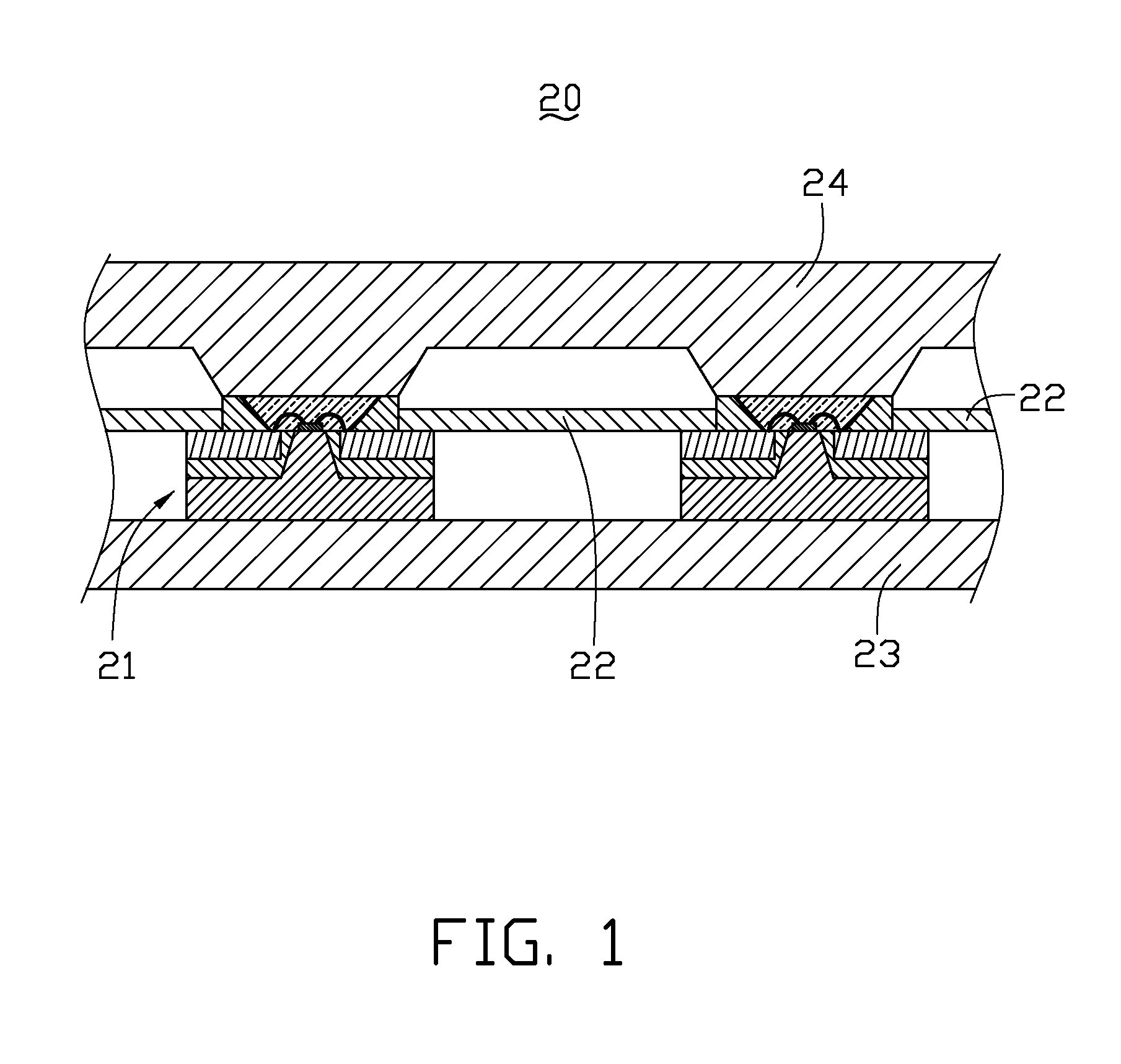
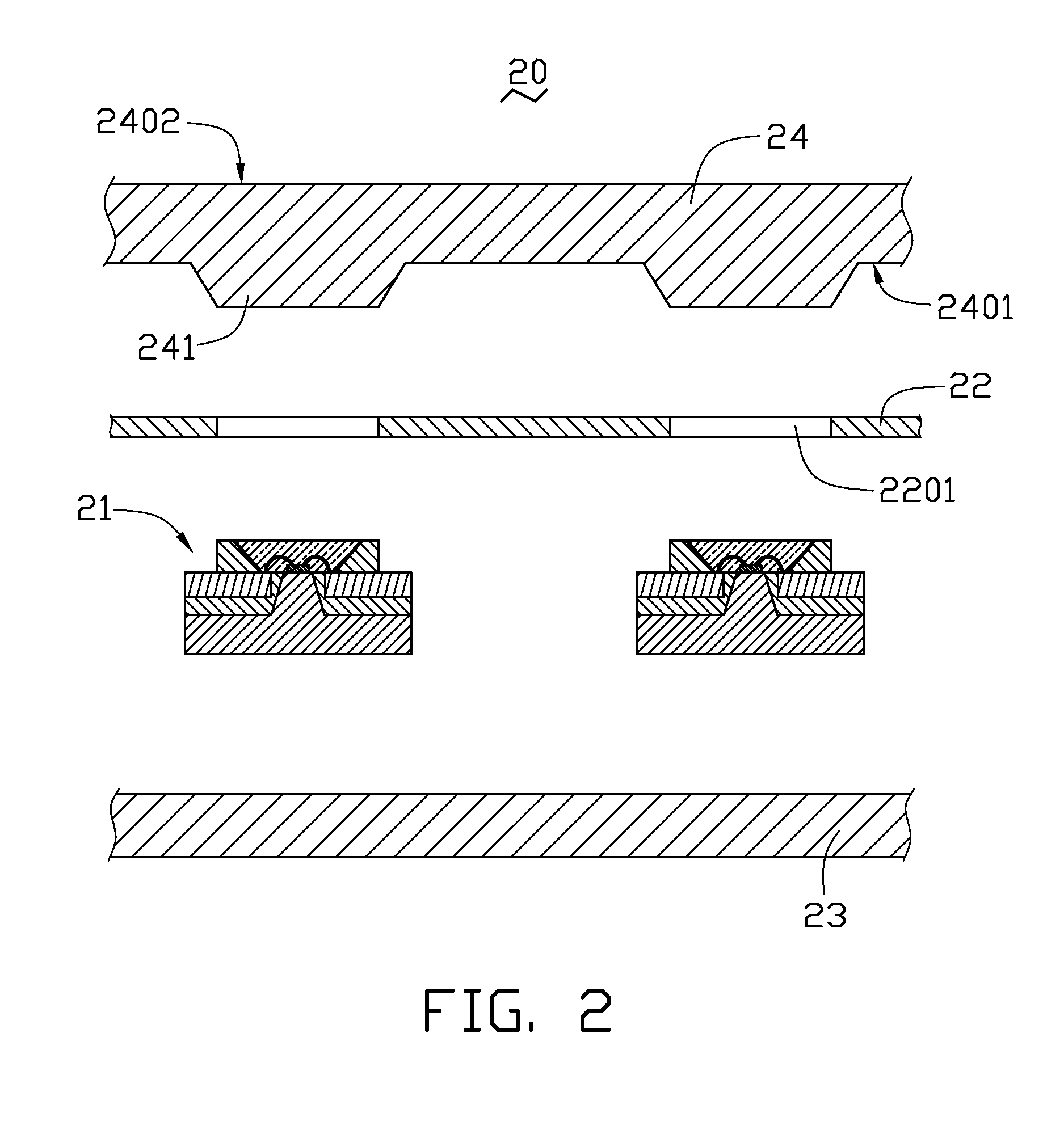
[0015]Referring to FIGS. 1 and 2, a light source device 20 includes a plurality of LED assemblies 21, a circuit member 22, a heat dissipation component 23, and an optical component 24. Each LED assembly 21 passes through the circuit member 22 and is positioned between the heat dissipation component 23 and the optical component 24. The circuit member 22 is electrically connected to the LED assemblies 21. The heat dissipation component 23 is spaced from the optical component 24.

[0016]The circuit member 22 may be a lead frame or a circuit board, such as a Flame Retardant 4 (FR4) printed circuit board (PCB), a bismaleimide-triazine resin PCB, or a metal-core PCB. The circuit member 22 may be a one-piece structure. A plurality of through holes 2201 is defined in the circuit member 22 to receive the LED assemblies 21.

[0017]The heat dissipation component 23 conducts heat generated by the LED assemblies 21 and dissipates the heat to outside of the light source device 20. The heat dissipatio...

second embodiment

[0026]Referring to FIG. 5, a light source device 30 is similar to the light source device 20 of FIGS. 1 to 4, except that the light source device 30 further includes a fixing component 35. The fixing component 35 includes a connection portion 350 and two clipping portions 352. The connection portion 350 passes through the circuit member 22 and the heat dissipation component 23. The two clipping portions 352 are positioned at two ends of the connection portion 350 and clip the circuit member 22 and the heat dissipation component 23.

third embodiment

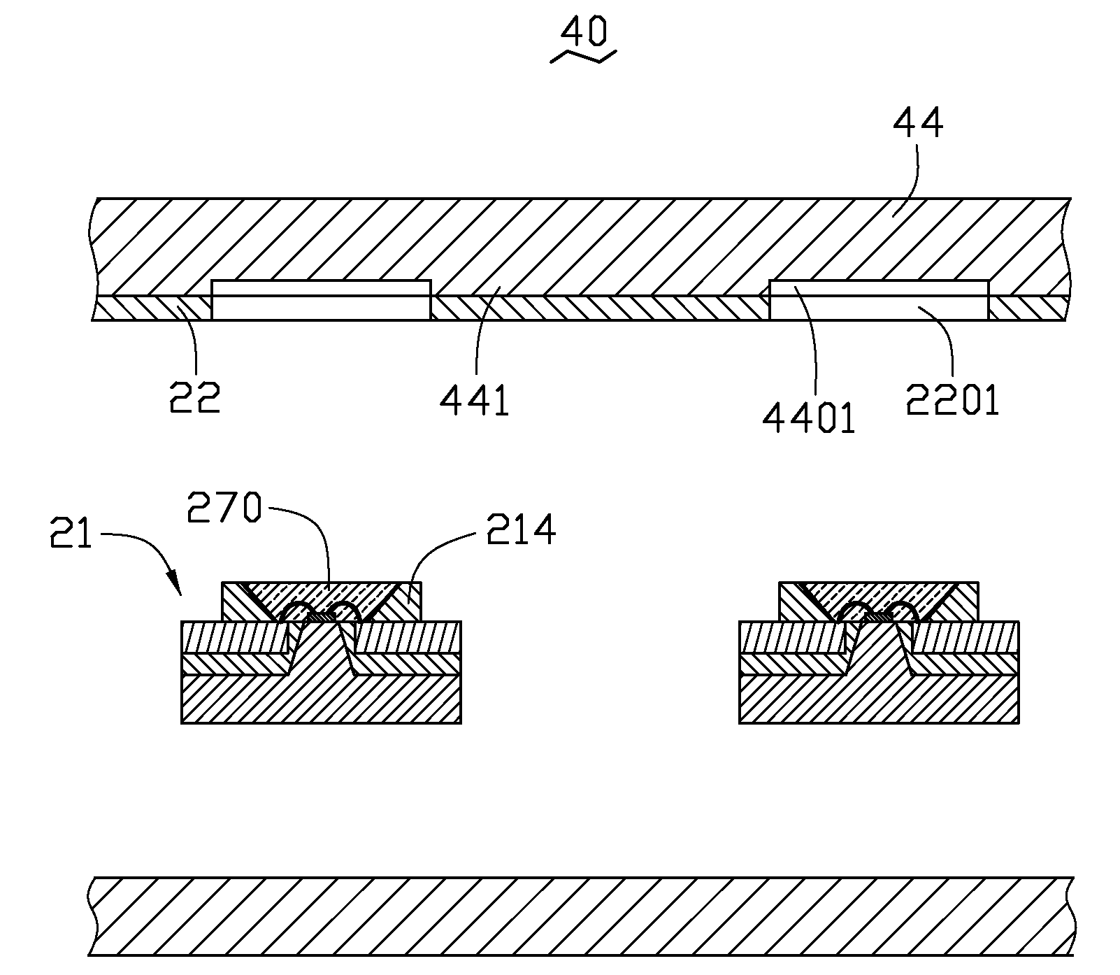
[0027]Referring to FIGS. 6 and 7, a light source device 40 is similar to the light source device 20 of FIGS. 1 to 4, except that the optical component 44 forms a plurality of spaced protrusions 441. Each protrusion 441 may be substantially rectangular shaped. A substantially rectangular recess 4401 is defined between adjacent protrusions 441. Each light reflecting portion 214 and each packaging member 270 pass through a corresponding through hole 2201 and are received in a corresponding recess 4401. The circuit member 22 contacts the plurality of spaced protrusions 441. In one embodiment, the circuit member 22 is a transparent circuit layer and contains indium tin oxide (ITO) material.


PUM


Abstract

A light source device includes a circuit member, a heat dissipation component, an optical component and light emitting diode assemblies. The circuit member defines spaced through holes. The light emitting diode assemblies have a first side and a second side opposite to the first side. Each light emitting diode assembly passes through a corresponding through hole and is electrically connected to the circuit member. The heat dissipation component contacts the first side, is spaced from the circuit member, and is configured to dissipate heat generated by the light emitting diode assemblies. The optical component contacts the second side, and is configured to distribute light emitted from the light emitting diode assemblies.

Description

BACKGROUND[0001]1. Technical Field[0002]The disclosure relates to a light source device.[0003]2. Description of Related Art[0004]Light emitting diodes (LEDs) are widely used as a light source for illumination due to their excellent characteristics, for example, a small volume, good optical properties, low energy consumption, and a long lifespan.[0005]A typical light source device includes a container, a cover, and LED assemblies. The LED assemblies are received in the container and covered by the cover. Each LED assembly includes a printed circuit board (PCB) and LEDs secured on the PCB. However, the container, the cover, and the PCB all have low heat conductivities, such that heat generated by the LED assemblies cannot be immediately dissipated.[0006]Therefore, a new light source device is desired to overcome the above-described shortcoming.BRIEF DESCRIPTION OF THE DRAWINGS[0007]Many aspects of the embodiments can be better understood with reference to the following drawings. The c...

Claims


Application Information

Patent Timeline
Patent Type & Authority Applications(United States)
IPC IPC(8): F21V29/00
CPCF21K9/00F21V29/70F21Y2101/02H01L33/60H01L33/64H05K1/021H05K1/182H05K2201/10106H05K2201/10477H05K2201/1056F21V29/006F21V19/003F21Y2105/001H01L2224/48091F21V29/004H01L2924/00014F21Y2105/10F21Y2115/10H01L2924/181F21V29/51H01L2924/00012
Inventor CHANG, CHUNG-MINLEE, TSE-AN
Owner ADVANCED OPTOELECTRONICS TECH
Why Eureka
Try Eureka