
Intelligent power system and methods for its application

a power system and intelligent technology, applied in the direction of electric energy management, modulated carrier systems, driver interactions, etc., can solve the problem that the general knowledge of the device which consumes energy is not generally known, and achieves the effect of reducing power level and improving carrier error rate in power channels

Inactive Publication Date: 2009-12-10
DOMINION ENERGY TECH +1
View PDF2 Cites 110 Cited by
  • Summary
  • Abstract
  • Description
  • Claims
  • Application Information

AI Technical Summary

Benefits of technology

[0007]The process for controlling a consumer device based upon information relating to characteristics of the power source may include sending a power signal to a power transceiver; embedding a signature into the power signal using a modulator to form a combined signal; transmitting the combined power signal to a consumer device; transmitting the signature and additional information to a server having records; storing the signature and the additional information in the records; demodulating the combined signal to determine the signature; sending the power from the power signal to a power supply coupled to the consumer device; generating a query based on the signature; sending the query to the server to request the server to lookup information in the records, by utilizing the signature as a primary key from which to request the additional information; or responding to the query by sending the additional information to the consumer device. The process may also include turning off the power supply if the information from the server indicates the power cost of power exceeds a predefined value; setting the consumer device to run in a power saving mode if the information from the server indicates the power exceeds a predefined value; turning on the power supply if the information from the server indicates the power is less than a predefined value; sending battery characteristics, user charge/discharge preferences, and vehicle-specific information to the consumer device; sending time-of-day restrictions and power cost information; or monitoring the characteristics of the power source to determine how much of the power comes from green sources, and instructing the controller to switch off or move certain electrical devices into a reduced power level if a certain percentage of the power does not come from green sources.
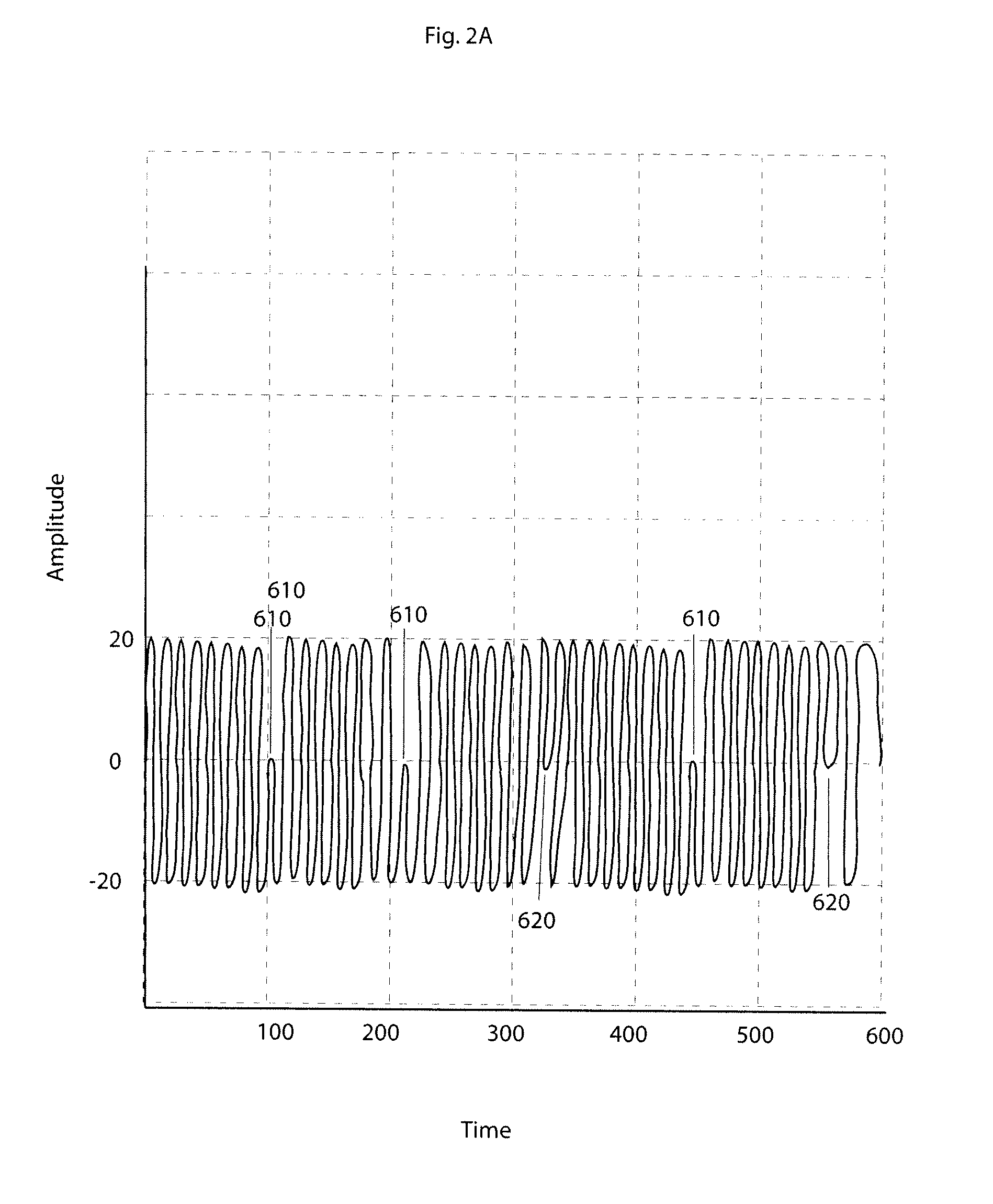
[0008]The process for embedding a signature into a power signal using OFDM may include: generating the signature; receiving a power signal having harmonics for transmitting power to a consumer device and for transmitting the signature to the consumer device; demultiplexing the signature into several sub-sequences; modulating the sub-sequences onto one or more carriers near the power signal using a modulator; wherein the step of modulating utilizes OFDM to embed the information into the carriers near the power signal. The power signal may comprise locations of peak and nonpeak spectral magnitude, and the step of modulating may add the sub-sequences to the carriers in the location of nonpeak magnitude. Additionally, the modulator may be instructed to use instantaneous phase or amplitude discontinuities to produce sub-channel modulation and improve carrier error rate in the power channel; the step of modulating uses minimum shift keying (MSK), binary PSK (BPSK), quadrature-carrier PSK (QPSK), or differential PSK (D-PSK) to produce the sub-channel modulation; the step of modulating may use frequency modulation to produce the sub-channel modulation; the step of modulating may use Amplitude Shift Keying (ASK) to produce the sub-channel modulation. In some embodiments, the embedded information may have a spectral containment of at least 90%; the embedded information may be embedded at a bandwidth of 5 Hz, 10 Hz, or 20 Hz; the embedded information can transfer information at 0.5 bits/Hz and 2.5 bits per second if the modulator is instructed to use binary phase shift keying at a bandwidth of 5 Hz; the embedded information can transfer information at 1.0 bits/Hz and 20 bits per second if the modulator i

Problems solved by technology

While power sources may monitor the consumption of energy, they do not generally know any information about the device which consume the energy.

Method used


Image

  • Intelligent power system and methods for its application
  • Intelligent power system and methods for its application
  • Intelligent power system and methods for its application

Examples


Embodiment Construction

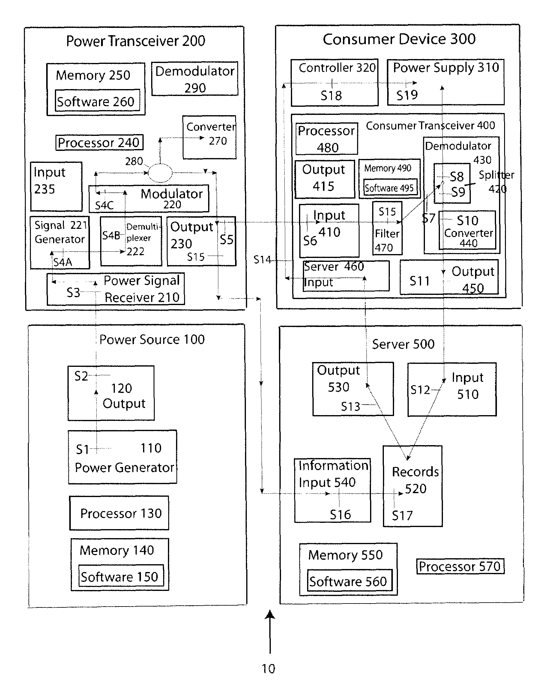
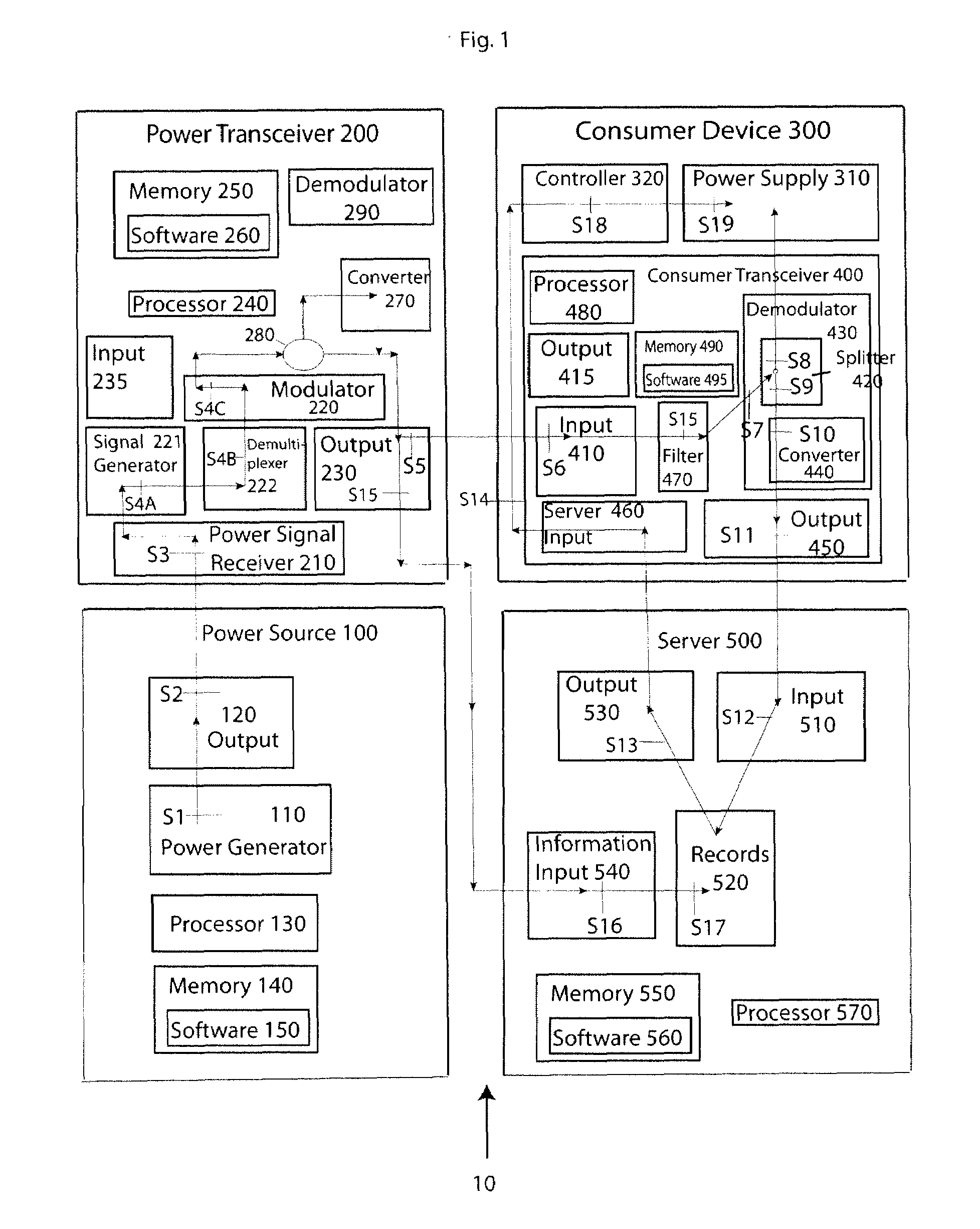
[0022]Aspects of the present invention provide a system 10 for intelligent power distribution. FIG. 1 illustrates a schematic view of an embodiment of the present invention comprising four components: a power source 100, a power transceiver 200, a consumer device 300, and a server 500. Various embodiments of the present invention may comprise a plurality of any of these components, and embodiments may be built without one more or of these components.

[0023]Power source 100 may be a large power generation facility such as the Hoover Dam, a local power facility such LILCO, PECO, or ConEdison, or a power generator such as the power generators made by Honeywell, Briggs and Stratton, or Generac. The power source 100 may also comprise a power generator 110 for generating a power signal 710 (FIG. 2C). The power signal may be transmitted to the power transceiver 200 via output 120, The power generator 100 may comprise the power transceiver 200 or they may be separate components as shown. The...


PUM


Abstract

Methods and systems for injecting information into a power signal, and techniques to capture the injected information are disclosed. Various processes for using the information are also presented, which may relate to the type of device receiving the information. Moreover, techniques for determining the distance of a consumer device are disclosed, as have a specific implementation which relates to mobile consumer devices. Also various ways of encrypting both in-band and out-of-band transmission are disclosed.

Description

FIELD OF THE INVENTION [0001]Aspects of the present invention relate to providing an intelligent system for distributing power to consumer devices. More specifically, the invention contemplates sending information concerning sending information in-band and out-of band.BACKGROUND OF THE INVENTION [0002]Typical power systems simply distribute power by generating power and allowing the power to flow from a location having a high voltage to an area of low voltage. While power sources may monitor the consumption of energy, they do not generally know any information about the device which consume the energy. Similarly, while the consumer devices can determine whether they are receiving power, they do not generally from what source they are receiving power. Aspects of the present invention overcome this and other problems.SUMMARY OF THE INVENTION [0003]In a first configuration of the present invention, a system is provided for distributing power. The system may contain a power source, a po...

Claims


Application Information

Patent Timeline
IPC IPC(8): H04B1/00H04L27/28H04B7/00
CPCY04S20/325Y04S20/40Y02B90/244H04L27/2626H04B2203/5412H04B2203/5433H04B3/546Y02B90/245Y02B90/242Y04S20/44Y04S20/327Y04S20/322Y02B90/243G01D4/004H04B2203/5458B60L2240/70B60L2250/16Y02T90/16Y02T10/7072Y02T90/14Y04S30/14B60L53/14B60L53/65B60L58/12B60L53/305B60L53/68Y02T10/70Y02T10/72Y02T90/12Y02T90/167Y04S20/30Y04S30/12G01D2204/12G01D2204/14G01D2204/16Y02B90/20
Inventor LOPORTO, JOHN J.MCCLELLAN, STAN
Owner DOMINION ENERGY TECH
Learn More