Apparatus For Producing Longitudinally Folded Products

a technology of products and apparatuses, applied in the direction of envelope/bag making machinery, paper/cardboard containers, transportation and packaging, etc., can solve the problems of insufficient flexibility of known arrangements of this type, inability to accommodate the side toward which the generated product was delivered, and inability to accommodate the side of the generated product in a simple manner, so as to increase flexibility and facilitate the passing of products. , the effect of increasing flexibility

Inactive Publication Date: 2009-12-10
MANROLANAD AG
View PDF17 Cites 2 Cited by
  • Summary
  • Abstract
  • Description
  • Claims
  • Application Information

AI Technical Summary

Benefits of technology

[0010]Another advantageous embodiment provides that each module contains a plurality of its own drive motors. In this way, not only the modules but also the individual units are autonomous with respect to driving means, which makes it possible to control speeds in an exact manner.
[0011]In a further advantageous development, all transporting and processing units have two tracks, the modules having side walls at a corresponding distance from one another. This further increases flexibility because one or two tracks can be operated regardless of the rotational position of the individual modules.
[0012]To further increase flexibility, the cross cutting device can have two cutting rollers which are associated with one another and which are mounted in rotatable eccentric bearings. This makes it possible to change the axial distance by rotating the eccentric bearings so that cutting rollers of different diameters can be used, which makes it possible to adapt the length of the folded products to be produced to individual cases.
[0013]According to another particularly preferred embodiment the splitting device has a stationary wedge which is constructed and arranged symmetrically with respect to the working plane and which engages between two guide plates which flank the wedge and which, together with the wedge, define a path fork which is symmetrical with respect to the working plane and opens downward. Two cam rollers which flank the guide plates and which are arranged symmetrically with respect to the working plane are associated with the guide plates, project through the respective adjacent guide plate in an alternating manner and, together with the other respective guide plate, form a feed for a belt guide associated with a branch flow. These steps advantageously result in a symmetrical construction of the splitting unit, and the cam rollers ensure a gentle handling of the passing products and a wear-free operation. Since there are no relative movements of the products with respect to the cam rollers, there is no risk of marks or smeared ink.
[0014]The cam rollers advantageously have along their length a plurality of cams which are arranged side by side at a distance from one another and the guide plates have a plurality of slots associated with the cams. This ensures a reliable, trouble-free operation regardless of the product width.
[0015]According to another advantageous embodiment the drive of the belt guides is derived from one of the existing motors and at least one belt roller of every belt guide is driven by means of an endless circulating member and is provided in the area of both ends with a driving element associated with the circulating member. Since drive elements which are symmetrical with respect to the center plane are provided at both ends of the driven belt rollers, each module can rotate easily.

Problems solved by technology

Therefore, if the side from which the web material arrived were changed, this could not be accommodated in a simple manner.
It was also not possible for the side toward which the generated product was delivered to be adapted to subsequent changing conditions.
Accordingly, known arrangements of this type proved to be insufficiently flexible.

Method used


Image

  • Apparatus For Producing Longitudinally Folded Products
  • Apparatus For Producing Longitudinally Folded Products
  • Apparatus For Producing Longitudinally Folded Products

Examples


Embodiment Construction

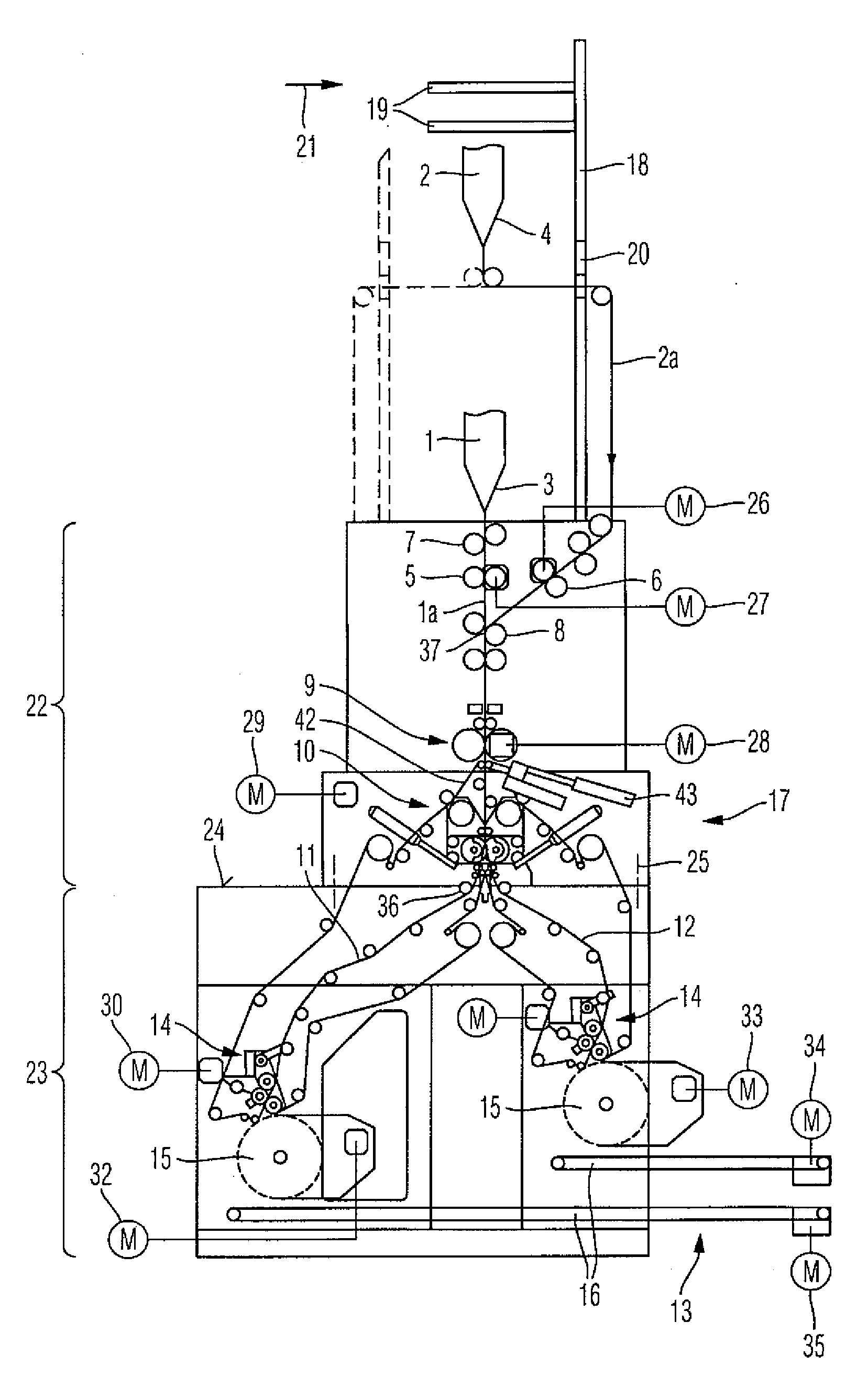
[0025]The apparatus shown in FIG. 1 serves to process web material, preferably in the form of printed paper substrate webs, to form longitudinally folded products in sheet form such as newspapers, etc. The web material 1, 2 in the form of individual webs or in the form of web packages comprising a plurality of webs placed one on top of the other is fed to the formers 3, 4 of a former arrangement and provided with a longitudinal fold in this way. A draw-in device 5, 6 which pulls the associated web material 1 and 2, respectively, over the associated formers 3 and 4, respectively, is associated with each former 3, 4. The draw-in devices 5, 6 comprise two rollers which cooperate with one another. One of the rollers is driven, and guiding and deflecting rollers 7, 8 can be arranged in front of it and / or in back of it.

[0026]The longitudinally folded material, designated hereinafter as webs 1a and 2a, respectively, is subsequently divided into products in sheet form by a cross cutting dev...


PUM

PropertyMeasurementUnit
areaaaaaaaaaaa
distanceaaaaaaaaaa
elasticaaaaaaaaaa

Abstract

An apparatus for producing longitudinally folded products has a machine frame (17) which is arranged below a former arrangement which can be charged with web material. Transporting and processing units are arranged in tandem in the machine frame (17), and a superstructure wall (18) which carries web guiding members (19) associated with the former arrangement is mounted on the machine frame (17). At least one web ribbon (2a) is guided through the superstructure wall (18). The machine frame (17) has at least two modules (22, 23) arranged one above the other which are rotatable by 180° relative to one another and can be connected to one another. Each module (22, 23) has its own at least one drive motor, and every unit provided in the region of the dividing line (24) between modules (22, 23) which are rotatable relative to one another is constructed symmetrically with respect to a center working plane containing the axis of rotation.

Description

BACKGROUND OF THE INVENTION[0001]1. Field of the Invention[0002]The invention is directed to an apparatus for producing longitudinally folded products having a machine frame which is arranged below a former arrangement. Transporting and processing units are arranged in tandem in the machine frame, and a superstructure wall which carries web guiding members associated with the former arrangement is mounted on the machine frame, at least one web ribbon being guided through the superstructure wall.[0003]2. Description of the Related Art[0004]In arrangements of the type mentioned above, the web guiding members must be easily accessible. Therefore, depending on the side at which the web material arrives, the superstructure wall carrying the web guiding members must be offset relative to one side or the other with respect to a center plane of the former arrangement. Formerly, in commonly used arrangements of this type the machine frame was constructed as a structural unit. Accordingly, th...

Claims


Application Information

Patent Timeline
Patent Type & Authority Applications(United States)
IPC IPC(8): B31B1/14B31F1/08
CPCB41F13/58B65H29/60B65H2402/10B65H45/28B65H45/221
Inventor SCHNELL, HELMUTSPATZ, URBAN
Owner MANROLANAD AG
Why Eureka
Try Eureka