Modeling And Management of Reservoir Systems With Material Balance Groups

a technology of material balance and reservoir system, applied in seimology for waterlogging, instruments, borehole/well accessories, etc., can solve the problems of large volume drop, time delay in any change, and further limitation of determinations

Active Publication Date: 2009-12-10
EXXONMOBIL UPSTREAM RES CO
View PDF12 Cites 40 Cited by
  • Summary
  • Abstract
  • Description
  • Claims
  • Application Information

AI Technical Summary

Benefits of technology

[0022]In one embodiment, a method of modeling a reservoir system is described. The method comprising constructing a reservoir model of a reservoir system, wherein the reservoir model comprises a reservoir and a plurality of wells; constructing at least one material balance group, wherein the at least one material balance group comprises a portion of at least one of the plurality of wells, a portion of the reservoir, and at least one well management algorithm to track material balance within the at least one material balance group; simulating fluid flow through the reservoir model based on the at least one material balance group by a simulator; and reporting results of the simulation.

Problems solved by technology

Because of the size of reservoirs and distance between wells, a time delay is present for any changes in the boundary conditions or operation of the wells.
As a result, the reservoir engineer as part of the well management strategy has to determine where to add producing wells (e.g. producers), what the producing wells rates are at certain times, where to add injecting wells (e.g. injectors), what are the compositions of the injecting wells, and what injecting well rates are at certain times. These determinations are further limited by numerous constraints that should be considered when setting appropriate boundary conditions.
Gases in the vapor phase tend to be lighter in molecular weight and are highly compressible with increases in pressure resulting in a large decrease in volume.
Because these are only estimates, the difference between production rates at the end of time step and the specified injection rates leads to an error in the material balance.
A VRR less than 1.0 indicates that the reservoir volume production is greater than reservoir injection volume, which often results in a decrease in the pressure within the reservoir.
Similarly, a VRR greater than 1.0 indicates that reservoir injection volume is greater than reservoir production volume, which often results in an increase in the reservoir pressure.
This approach introduces some error in reservoir volume calculations, which also affects VRR calculations and pressure maintenance calculations.
Accordingly, typical methods of well management have problems with injector allocation-for voidage replacement or pressure maintenance, because they use different pressures at injectors and producers for computing reservoir volumes, unreliable and potentially unstable methods for setting injector rates and neglecting material balance errors that develop because of the discretization of time in the simulator.
With regard to the problems of injector allocation for voidage replacement or pressure maintenance, the problem is further complicated when injecting vapor phase by the fact that produced hydrocarbons are heavier than the injected vapor or gases.
However, this method does not appear to address how to set injection rates to maintain pressure or maintain a target VRR.
However, this matching of the target pressure in this method is deficient because it does not appear to account for pressure variations across the reservoir, fluid behavior affects or time stepping errors.
Rate changes that increase in magnitude as the time step size is reduced can lead to numerical instabilities in the simulation.
Also, rapid changes in rates can lead to overshooting the target pressure.
If the overshoots grow in size, this can again lead to instabilities in the simulation.
Accordingly, with a more realistic model, which utilizes dynamic time step sizes, the algorithm is likely fail because the corrective term causes the model to be unstable.
Another problem in previous methods is that they appear to fail to honor the material balance of injecting fluids over time.
As a result, this under injecting may lead to under estimating production rates.
Other well management algorithms define groups of wells, but are deficient because they do not couple reservoir behavior directly with well management strategy.
While this application does disclose grouping of wells, which may contain sub-groupings of wells up to several layers, these groupings. do not incorporate reservoir behavior with well management strategy.

Method used


Image

  • Modeling And Management of Reservoir Systems With Material Balance Groups
  • Modeling And Management of Reservoir Systems With Material Balance Groups
  • Modeling And Management of Reservoir Systems With Material Balance Groups

Examples


Embodiment Construction

[0044]In the following detailed description section, the specific embodiments of the present techniques are described in connection with preferred embodiments. However, to the extent that the following description is specific to a particular embodiment or a particular use of the present techniques, this is intended to be for exemplary purposes only and simply provides a concise description of the exemplary embodiments. Accordingly, the invention is not limited to the specific embodiments described below, but rather, it includes all alternatives, modifications, and equivalents falling within the true scope of the appended claims.

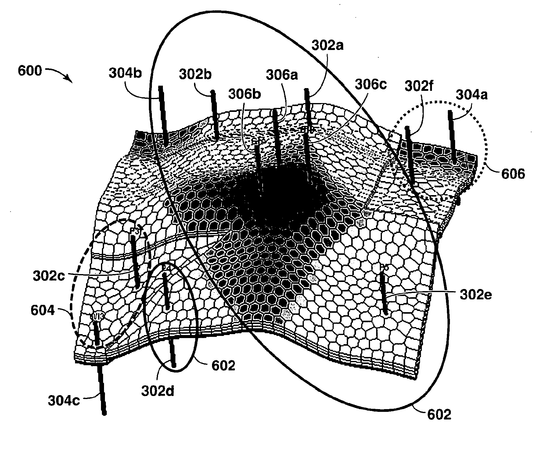
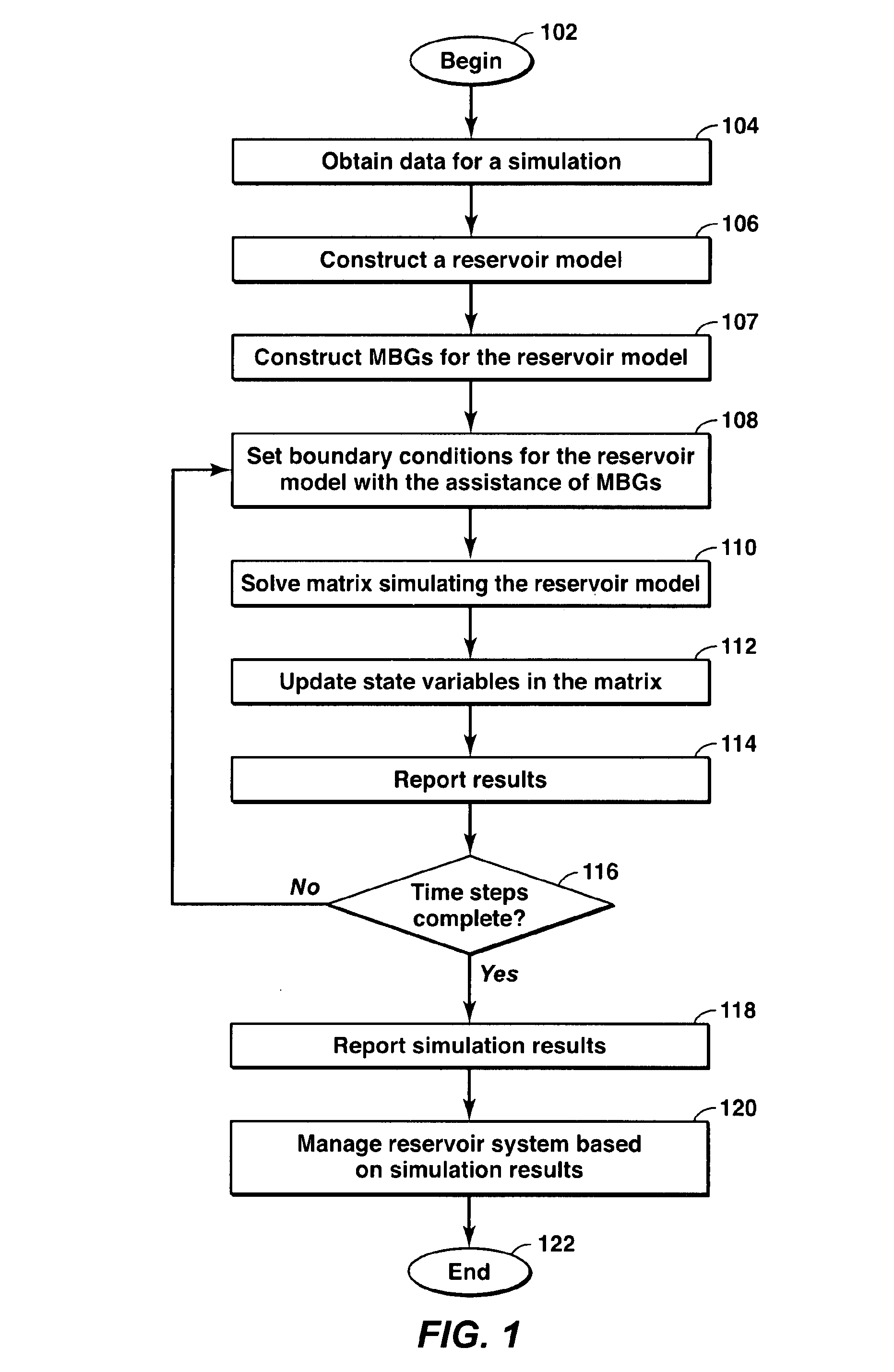
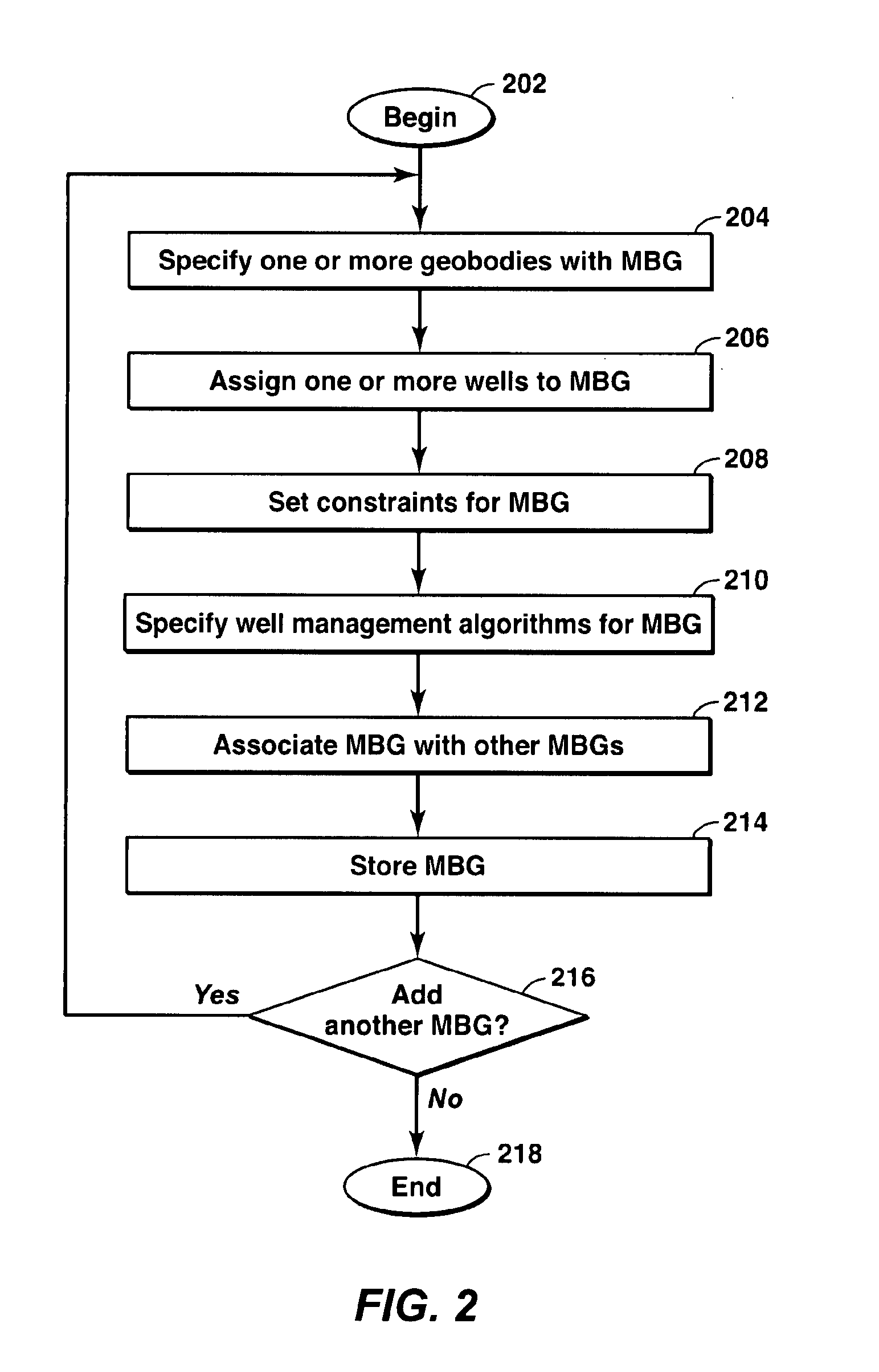
[0045]The present technique is directed to a method or system for modeling and managing a hydrocarbon reservoir. Under the present techniques, material balance groups (MBGs), which are software representations of logic and algorithms, are utilized to develop and to implement a well management strategy in a reservoir simulator for a reservoir system. MBGs may ...


PUM


Abstract

Methods and systems for modeling a reservoir system are described. The method includes constructing a reservoir model of a reservoir system. The reservoir model includes a reservoir and a plurality of wells. Also, one or more material balance groups are constructed with each material balance group having a portion of at least one of the plurality of wells, a portion of the reservoir, and at least one well management algorithm to track material balance within the respective material balance group. Then, fluid flow through the reservoir model is simulated based on the material balance groups by a simulator and the results are reported.

Description

CROSS REFERENCE TO RELATED APPLICATIONS[0001]This application claims the benefit of U.S. Provisional Application No. 60 / 855,653, filed Oct. 31, 2006.FIELD OF THE INVENTION[0002]The present invention describes a method for modeling and managing reservoir systems with material balance groups (MBGs). In particular, the present invention describes modeling reservoir systems in a reservoir simulator that uses MBGs to apply well management algorithms to the reservoir system model to effectively manage the operation of the reservoir system.BACKGROUND[0003]This section is intended to introduce various aspects of art, which may be associated with exemplary embodiments of the present techniques. This discussion is believed to provide information that facilitates a better understanding of particular aspects of the present techniques. Accordingly, it should be understood that this section should be read in this light, and not necessarily as admissions of prior art.[0004]The production of hydroc...

Claims


Application Information

Patent Timeline
Patent Type & Authority Applications(United States)
IPC IPC(8): G06G7/50G06F17/11G06G7/66
CPCE21B49/00E21B43/00E21B43/12E21B49/087G01V1/40
Inventor DAVIDSON, JEFFREY E
Owner EXXONMOBIL UPSTREAM RES CO
Why Eureka
Try Eureka