Online estimation of cathode inlet and outlet rh from stack average hfr

a technology of cathode inlet and outlet rh and stack average, which is applied in the direction of electrochemical generators, instruments, and mechanical means, can solve the problems of increasing the size of the hole in the membrane, limiting the life of the membrane, and relatively expensive manufacturing of the membrane, so as to minimize the error and high frequency resistance

Active Publication Date: 2011-05-19
GM GLOBAL TECH OPERATIONS LLC
View PDF5 Cites 19 Cited by
  • Summary
  • Abstract
  • Description
  • Claims
  • Application Information

AI Technical Summary

Problems solved by technology

MEAs are relatively expensive to manufacture and require certain conditions for effective operation.
For stack durability purposes, it is desirable to minimize the number of relative humidity cycles of the membrane because cycling between RH extremes has been shown to severely limit membrane life.
This expansion and contraction of the membrane causes pin holes in the membrane, which create hydrogen and oxygen cross-over through the membrane creating hot spots that further increase the size of the hole in the membrane, thus reducing its life.
At low cell power demands, typically below 0.2 A / cm2, the water may accumulate within the flow channels because the flow rate of the reactant gas is too low to force the water out of the channels.
Those areas of the membrane that do not receive reactant gas as a result of the channel being blocked will not generate electricity, thus resulting in a non-homogenous current distribution and reducing the overall efficiency of the fuel cell.
As more and more flow channels are blocked by water, the electricity produced by the fuel cell decreases, where a cell voltage potential less than 200 mV is considered a cell failure.
While controlling fuel cell stack membrane humidification using RHavg may be sufficient to meet efficiency targets, it is the presence of liquid water in the cathode inlet flow channels and the cathode outlet flow channels that directly correlates to poor reliability, durability and damage caused by freezing in a fuel cell system.
However, this approach requires the use of inlet RH sensors which are prone to failing in the presence of liquid water, thus, flooding or over drying of the fuel cell stack may result.
Thus, errors in temperature, air flow and current management can result in poor control of the humidification of the fuel cell stack.

Method used


Image

  • Online estimation of cathode inlet and outlet rh from stack average hfr
  • Online estimation of cathode inlet and outlet rh from stack average hfr
  • Online estimation of cathode inlet and outlet rh from stack average hfr

Examples


Embodiment Construction

[0020]The following discussion of the embodiments of the invention directed to a method for estimating a cathode inlet and cathode outlet relative humidity by measuring the high frequency resistance of a fuel cell stack is merely exemplary in nature, and is in no way intended to limit the invention or its applications or uses.

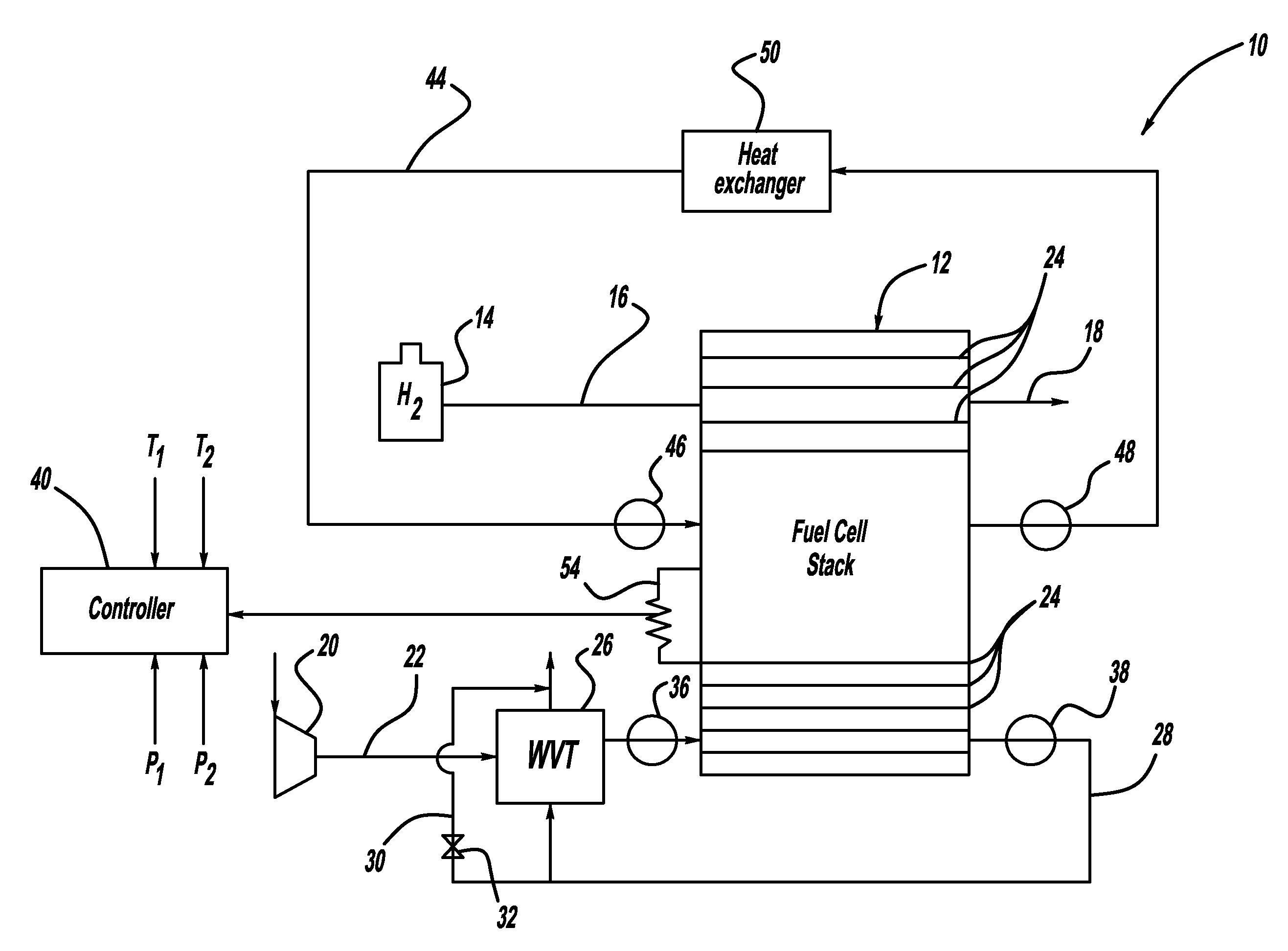
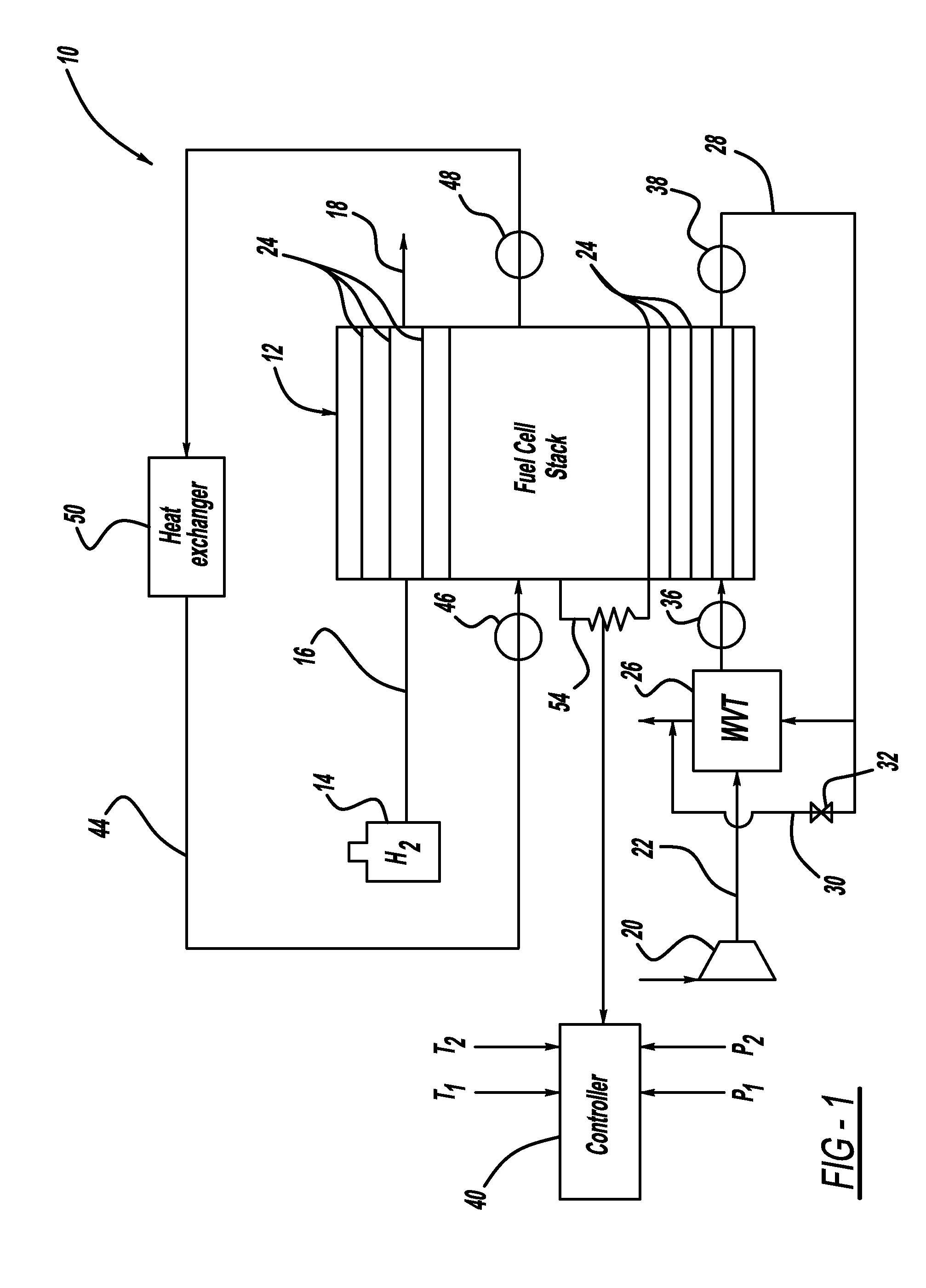
[0021]FIG. 1 is a schematic block diagram of a fuel cell system 10 including a fuel cell stack 12. The fuel cell stack 12 includes a plurality of fuel cells 24 where each fuel cell 24 includes a membrane electrode assembly (MEA) separated from each other by electrically conductive, liquid-cooled bipolar separator plates (not shown). The fuel cell stack 12 receives hydrogen from a hydrogen source 14 on anode input line 16 and provides an anode exhaust gas on line 18. A compressor 20 provides an air flow to the cathode side of the fuel cell stack 12 on cathode input line 22 through a water vapor transfer (WVT) unit 26 that humidifies the cathode input air. A cath...


PUM

PropertyMeasurementUnit
cell voltage potentialaaaaaaaaaa
relative humidityaaaaaaaaaa
RHaaaaaaaaaa

Abstract

A method for estimating cathode inlet and cathode outlet relative humidity (RH) of a fuel cell stack. The method uses a model to estimate the high frequency resistance (HFR) of the fuel cell stack based on water specie balance, and also measures stack HFR. The HFR values from the estimated HFR and the measured HFR are compared, and an error between the HFR values is determined. An online regression algorithm is then utilized to minimize the error and the solution of the regression is the RH profile in the stack including the cathode inlet and outlet relative humidities.

Description

BACKGROUND OF THE INVENTION[0001]1. Field of the Invention[0002]This invention relates generally to a method for estimating fuel cell stack cathode inlet and cathode outlet relative humidity (RH) from stack high frequency resistance (HFR) and, more particularly, to a method for measuring the HFR of a stack, estimating a model HFR of the stack, minimizing an error between the fuel cell measured HFR and the model HFR, and using a water specie balance to estimate cathode inlet and cathode outlet RH.[0003]2. Discussion of the Related Art[0004]Hydrogen is a very attractive fuel because it is clean and can be used to efficiently produce electricity in a fuel cell. A hydrogen fuel cell is an electro-chemical device that includes an anode and a cathode with an electrolyte therebetween. The anode receives hydrogen gas and the cathode receives oxygen or air. The hydrogen gas is dissociated at the anode catalyst to generate free protons and electrons. The protons pass through the electrolyte t...

Claims


Application Information

Patent Timeline
Patent Type & Authority Applications(United States)
IPC IPC(8): G01N19/10
CPCH01M8/04358H01M8/04395H01M8/0441Y02E60/50H01M8/04843H01M8/04977H01M2008/1095H01M8/04835H01M8/04952H01M8/04992
Inventor SINHA, MANISH
Owner GM GLOBAL TECH OPERATIONS LLC
Why Eureka
Try Eureka