Managing Migration of a Shared Memory Logical Partition from a Source System to a Target System

a logical partition and shared memory technology, applied in the field of data processing systems, can solve the problems of difficult to fully utilize the available resources of the partitioned server, cumbersome and inconvenient, and inability to fully utilize the memory in this way

Active Publication Date: 2009-12-10
IBM CORP
View PDF92 Cites 74 Cited by
  • Summary
  • Abstract
  • Description
  • Claims
  • Application Information

AI Technical Summary

Benefits of technology

[0006]To address this need, the concept of a shared memory partition has been created. A shared memory partition's memory is backed by a pool of hypervisor-managed physical memory in the server that is shared by other shared memory partitions on that server. The amount of physical memory in the pool is typically smaller than the sum of the logical memory assigned to all of the shared memory partitions in the pool to allow the memory to be more fully utilized. Idle and / or less active logical memory in the shared partitions that does not fit in the physical memory pool is paged out by the hypervisor to a cheaper and more abundant form of paging storage (i.e., the paging devices) via an entity external to the hypervisor known as a paging service partition. In one implementation, the paging device(s) are defined in one or more physical storage disks. Disclosed herein are automated processes for facilitating live migration of a shared memory logical partition between shared memory partition data processing systems.

Problems solved by technology

Partitioned computing platforms have led to challenges to fully utilize available resources in the partitioned server.
Flexibility may be added by allowing the user to dynamically remove and add resources, however, this requires active user interaction, and can therefore be cumbersome and inconvenient.
Also, memory is difficult to fully utilize in this way since there are frequently large amounts of infrequently accessed memory in idle partitions.
However, that memory needs to be available to the operating system(s) to handle sudden spikes in workload requirements.

Method used


Image

  • Managing Migration of a Shared Memory Logical Partition from a Source System to a Target System
  • Managing Migration of a Shared Memory Logical Partition from a Source System to a Target System
  • Managing Migration of a Shared Memory Logical Partition from a Source System to a Target System

Examples


Embodiment Construction

[0022]Before describing various automated processes for facilitating migration of a logical partition between shared memory data processing systems (in accordance with aspects of the present invention), shared memory partitions and shared memory partition data processing systems are discussed below with reference to FIGS. 1-4.

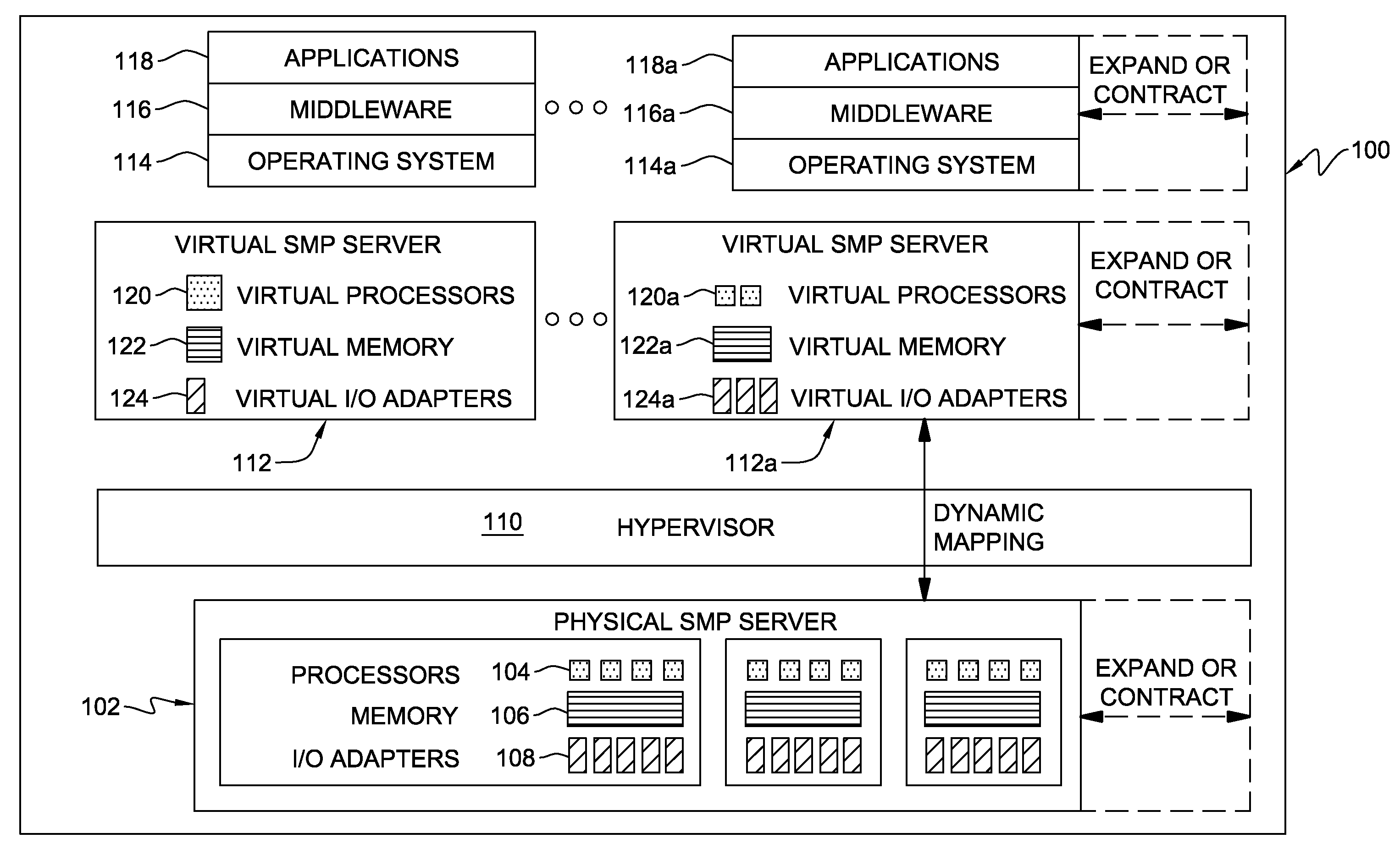
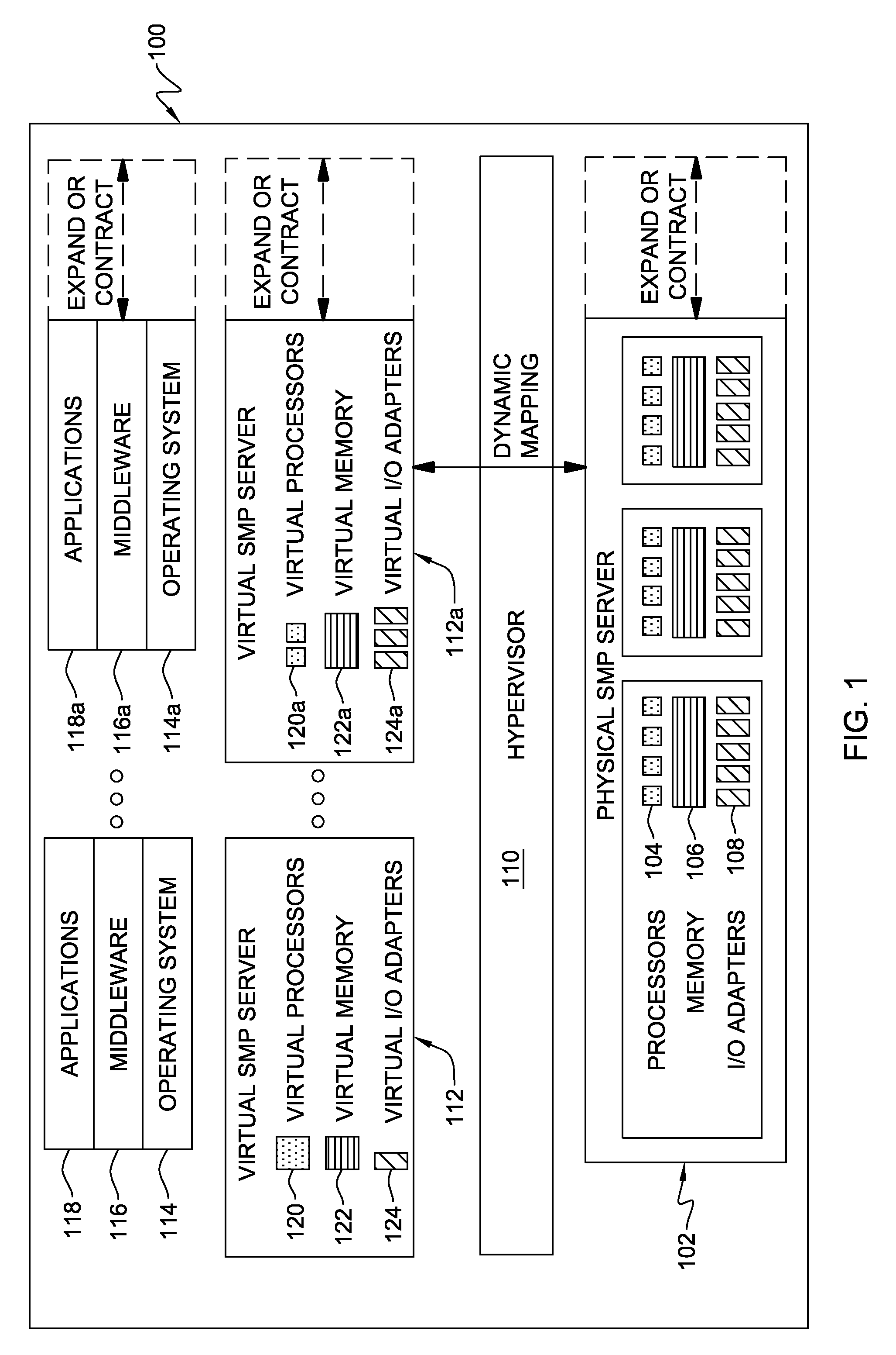
[0023]FIG. 1 is a block diagram of a data processing system 100, which in one example, is a symmetric multiprocessing (SMP) server computer system. SMP server computer system 100 includes physical hardware devices that can be mapped to, i.e., temporarily owned by, a user application to execute that application.

[0024]SMP server computer system 100 includes a physical SMP server 102. Physical SMP server 102 includes physical hardware devices such as processor 104, memory 106, and I / O adapters 108. These physical devices are managed by hypervisor 110. Processors 104 are shared processors and each may be a simultaneous multithreading (SMT)-capable processor that is...


PUM


Abstract

Migration management is provided for a shared memory logical partition migrating from a source system to a target system. The management approach includes managing migration of the logical partition from the source system to the target system by: transferring a portion of logical partition state information for the migrating logical partition from the source system to the target system by copying at the source system contents of a logical page of the migrating logical partition into a state record buffer for forwarding to the target system; forwarding the state record buffer to the target system; and determining whether the migrating logical partition is suspended at the source system, and if not, copying at the target system contents of the state record buffer to paging storage of the target system, the paging storage being external to physical memory managed by a hypervisor of the target system.

Description

CROSS-REFERENCE TO RELATED APPLICATION [0001]This application claims the benefit of U.S. provisional application Ser. No. 61 / 059,492, filed Jun. 6, 2008, entitled “Virtual Real Memory”, the entirety of which is incorporated herein by reference.TECHNICAL FIELD [0002]The present invention relates generally to data processing systems, and more particularly, to facilitating migration of a shared memory logical partition between shared memory partition data processing systems.BACKGROUND OF THE INVENTION [0003]Logical partitions (LPARs) running atop a hypervisor of a data processing system are often used to provide higher-level function than provided by the hypervisor itself. For example, one LPAR may be designated a virtual input / output server (VIOS), which provides input / output (I / O) services to one or more other LPARs of the data processing system. This offloading of higher-level function avoids complex code in the hypervisor, and thus, assists in maintaining the hypervisor small and s...

Claims


Application Information

Patent Timeline
Patent Type & Authority Applications(United States)
IPC IPC(8): G06F12/02G06F12/00G06F12/16G06F9/455
CPCG06F11/0712G06F11/073G06F11/0724G06F11/0793G06F11/0745
Inventor JACOBS, STUART Z.LARSON, DAVID A.OUREN, WADE B.VOSSEN, KENNETH C.
Owner IBM CORP
Why Eureka
Try Eureka