Egr system with dedicated egr cylinders

a technology of egr cylinders and egr cylinders, which is applied in the direction of electrical control, process and machine control, instruments, etc., can solve the problems of difficult control accuracy and reduce the production of nox

Active Publication Date: 2009-12-17
SOUTHWEST RES INST
View PDF20 Cites 199 Cited by
  • Summary
  • Abstract
  • Description
  • Claims
  • Application Information

AI Technical Summary

Problems solved by technology

EGR is generally controlled by a combination of different parameters such as exhaust backpressure, engine coolant temperature, engine speed, throttle position or manifold pressure and has proven difficult to control accurately.
The dilution of the oxygen present in the combustion chamber reduces the production of NOx.

Method used


Image

  • Egr system with dedicated egr cylinders
  • Egr system with dedicated egr cylinders
  • Egr system with dedicated egr cylinders

Examples


Embodiment Construction

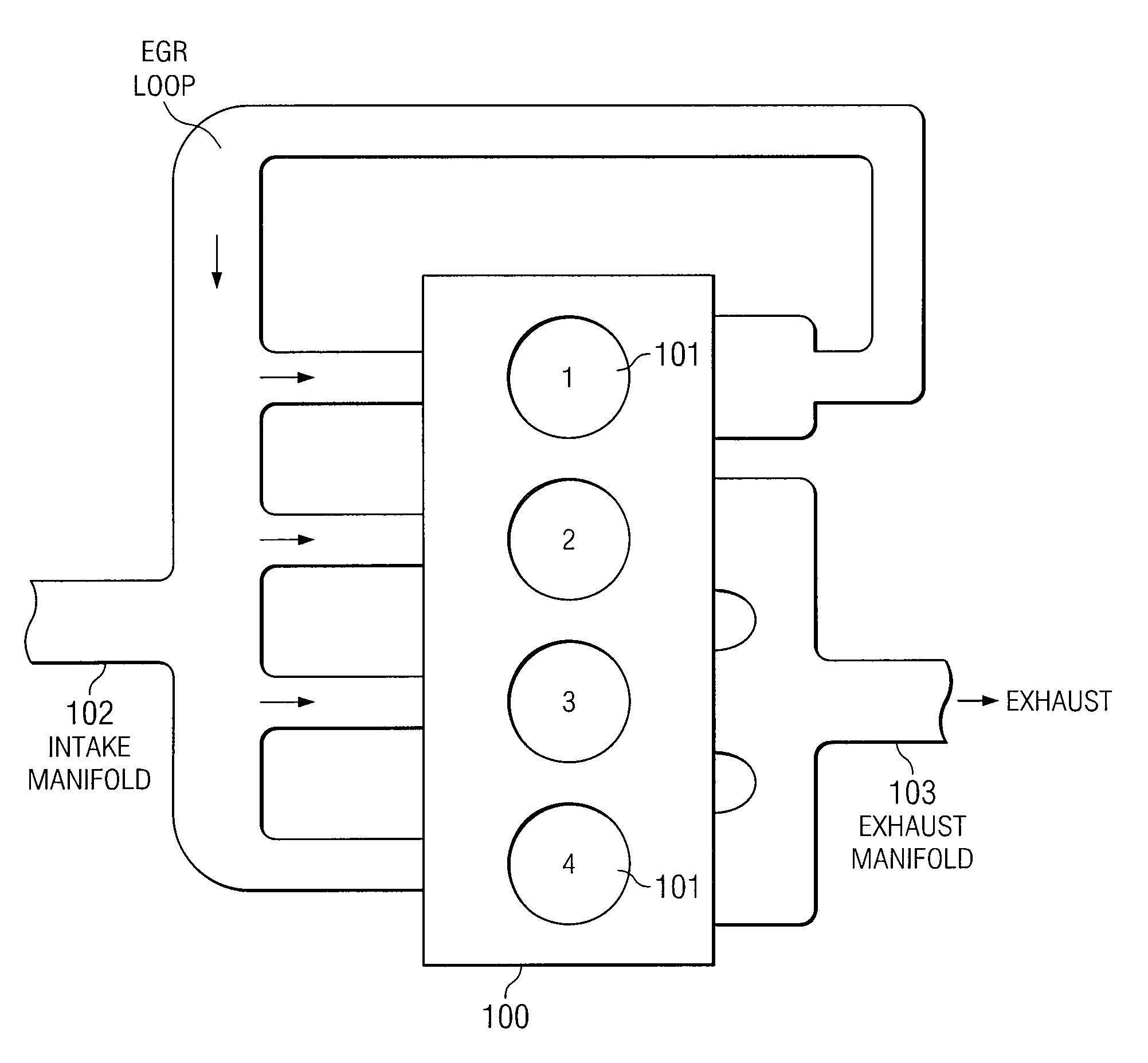
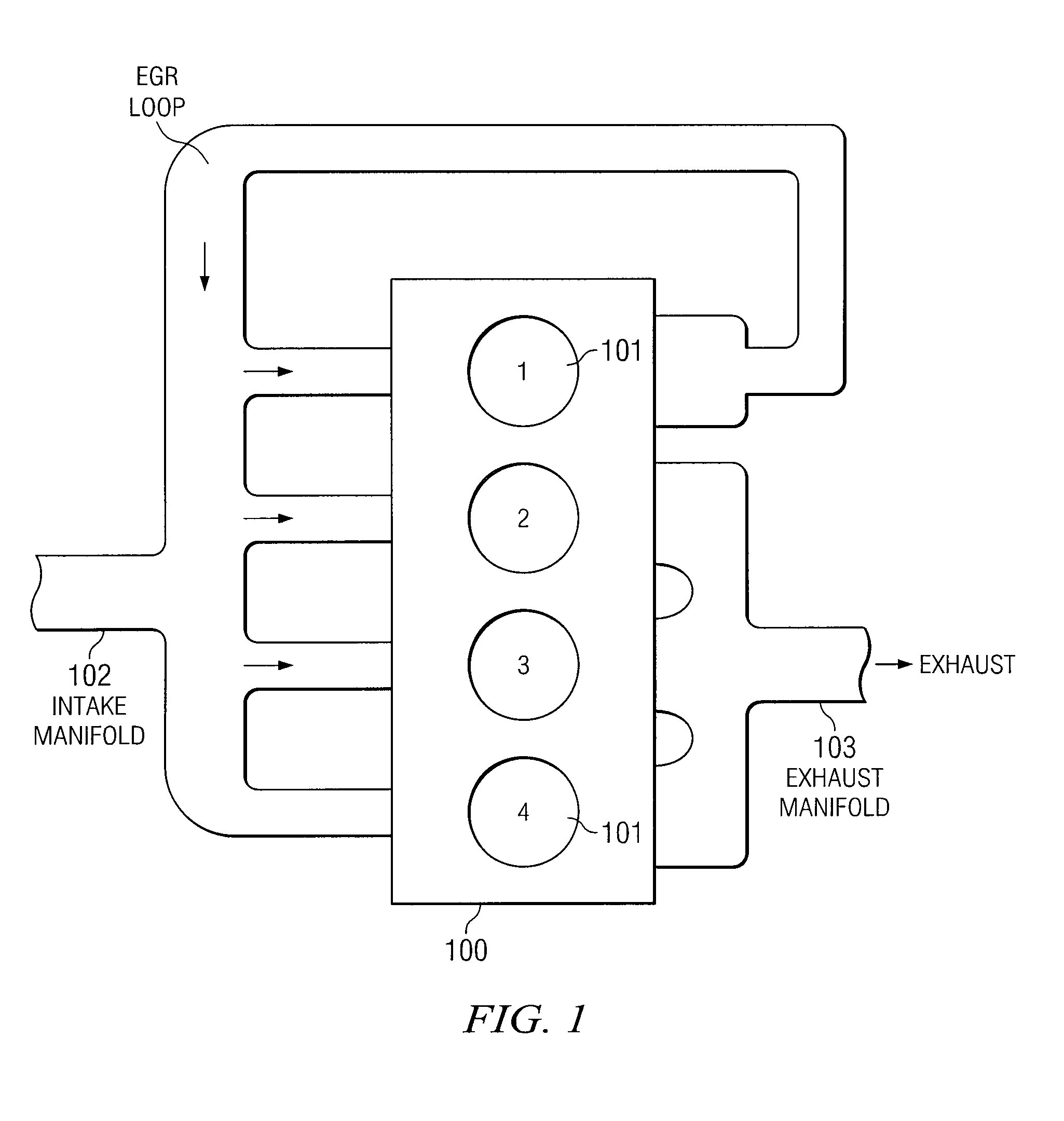
[0012]The following description is directed to various configurations of an EGR system implemented in an internal combustion engine system. One or more cylinders of the internal combustion engine is used to generate the exhaust gas that will be recirculated and used as a diluent for the intake charge of the entire engine. The use of one or more cylinders to generate its entire output of exhaust for recirculation is referred to herein as use of “dedicated EGR cylinder(s)”.

[0013]FIG. 1 illustrates an internal combustion engine 100 having four cylinders 101 (referenced as cylinders 1-4). One of the cylinders 101 is a dedicated EGR cylinder, that is, 100% of its exhaust is recirculated back to the intake manifold. The exhaust of the other three cylinders 101 is directed to an exhaust system. In this example, the engine is said to have “25% dedicated EGR” because one of its four cylinders has 100% of its exhaust redirected to the intake manifold 102.

[0014]Experiments have shown that if t...


PUM


Abstract

Improved exhaust gas recirculation system and methods that use one or more of the engine's cylinders as dedicated EGR cylinders. All of the exhaust from the dedicated EGR cylinders is recirculated back to the engine intake. Thus, the EGR rate is constant, but the EGR mass flow may be controlled by adjusting the air-fuel ratio of the dedicated EGR cylinders or by using various variable valve timing techniques.

Description

TECHNICAL FIELD OF THE INVENTION[0001]This invention relates to internal combustion engines, and more particularly to an improved exhaust gas recirculation system for such engines.BACKGROUND OF THE INVENTION[0002]For control of internal combustion engines, three important control parameters are spark timing (or fuel injection timing in a diesel engine), the exhaust gas recirculation (EGR) rate, and the air / fuel ratio (AFR). Control of spark timing or injection timing affects the timing of the initiation of the combustion process. Control of EGR and AFR affects the speed and duration of the combustion process.[0003]The AFR is often controlled by an exhaust oxygen sensor to produce a desired AFR in a closed loop system. EGR is generally controlled by a combination of different parameters such as exhaust backpressure, engine coolant temperature, engine speed, throttle position or manifold pressure and has proven difficult to control accurately. Spark or injection timing is generally de...

Claims


Application Information

Patent Timeline
Patent Type & Authority Applications(United States)
IPC IPC(8): F02D45/00
CPCF02B29/0412F02D13/0238F02D13/0261F02D41/0065F02D41/008F02D2041/001Y02T10/18F02M25/0711F02M25/0732F02M25/074F02M25/0749F02M25/0752Y02T10/47F02M25/0707F02M26/43F02M26/05F02M26/08F02M26/24F02M26/35F02M26/01Y02T10/12Y02T10/40
Inventor ALGER, II, TERRENCE FRANCISMANGOLD, BARRETT WADEGINGRICH, JESS WITMANMEHTA, DARIUS
Owner SOUTHWEST RES INST
Why Eureka
Try Eureka