Positioning apparatus, positioning method, exposure apparatus, device manufacturing method, and methods of manufacturing positioning apparatus and exposure apparatus

a technology of positioning apparatus and positioning method, which is applied in the direction of measurement devices, instruments, photomechanical treatment, etc., can solve the problems of difficult to correct the displacement of optical elements, change the relative position relationship, and limited movable range, so as to achieve accurate measurement of the position of a measurement portion

Inactive Publication Date: 2009-12-17
CANON KK
View PDF15 Cites 18 Cited by
  • Summary
  • Abstract
  • Description
  • Claims
  • Application Information

AI Technical Summary

Benefits of technology

[0016]The present invention makes it possible to provide a position measurement device

Problems solved by technology

In addition, a mounting error of the position measurement mechanism can change the relative positional relationship between a position detecting mechanism and the measurement portion.
However, it is difficult to correct the displacement of an optical element caused by, for example, surface-deformation-drive or an assembling error by the actuator placed on the rear surface of the optical element, because the movable range is limited.
In the calibration method disclosed in Japanese Patent Laid-Open No. 2002-324752, however, the position or surface shape of an optical element is not always strictly adjusted.
That is, even when the adjustment amount of the driving element is accurate, it is impossible to guarantee that an optical element is accurately moved to a state in which the optical characteristics are

Method used


Image

  • Positioning apparatus, positioning method, exposure apparatus, device manufacturing method, and methods of manufacturing positioning apparatus and exposure apparatus
  • Positioning apparatus, positioning method, exposure apparatus, device manufacturing method, and methods of manufacturing positioning apparatus and exposure apparatus
  • Positioning apparatus, positioning method, exposure apparatus, device manufacturing method, and methods of manufacturing positioning apparatus and exposure apparatus

Examples


first embodiment

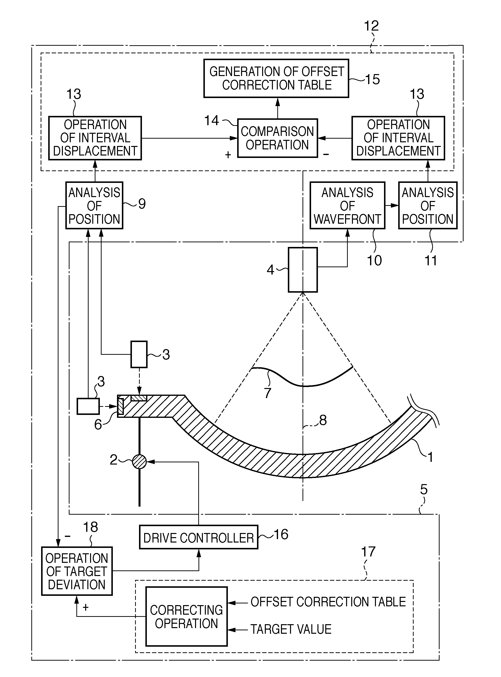
[0040]FIG. 1 is a view showing an example of the arrangement of an optical element positioning apparatus according to the first embodiment of the present invention. This positioning apparatus is incorporated into, for example, an exposure apparatus. An exemplary arrangement of the positioning apparatus includes an optical element 1 to be controlled, a driving device 2 for displacing a drive portion, a portion to be driven, or a portion to which a driving force is applied, of the optical element 1, a position measurement device 3 for measuring the position of a measurement portion of the optical element 1, a wavefront measurement device 4 for measuring the wavefront of light guided by the optical element 1, and a controller 5.

[0041]The optical element 1 is, for example, a concave mirror in a projection optical system of an exposure apparatus. The driving device 2 includes an actuator, and can perform positioning for at least one of a total of six degrees of freedom including three de...

second embodiment

[0080]In the first embodiment, the Z-axis direction displacement conversion expression represented by equation (4) used in the position analysis unit 11 contains an error produced by approximation. Examples of the error factor are an error on the surface of projection from the normal line direction to the optical axis direction, and a fitting error in Zernike analysis. Although the former error can be decreased by increasing the density of data, the density of an area sensor must be increased. In this case, the amount of data to be processed becomes enormous, and this very increases the load of processing. Therefore, the former error cannot unlimitedly be reduced. For the latter error, a more complete function is obtained by increasing the order of the Zernike polynomial for fitting, and an error of the obtained coefficient also decreases. However, the processing load naturally becomes enormous, and this makes the method impractical. Therefore, the second embodiment taking account o...

third embodiment

[0084]The third embodiment of the present invention is an embodiment in which a wavefront to be processed by a wavefront analysis unit 10 is the wavefront of the optical axis coordinate system. In this case, the wavefront of the normal line coordinate system can be calculated by performing coordinate conversion on the wavefront of the optical axis coordinate system obtained by wavefront measurement. Also, a position analysis unit 11 can use the same conversion expression as equations (6). Thus, a position measurement device 3 can be accurately calibrated in the same manner as in the second embodiment.


PUM


Abstract

A positioning apparatus comprises a controller for controlling a driving device, and positions a measurement portion of an optical element. The controller displaces a drive portion of the optical element by a specific operation of the driving device, and calculate a displacement of the optical element as a first displacement based on an output from a position measuring device, calculate a displacement of the optical element caused by the specific operation as a second displacement, based on an output from a wavefront measuring device configured to measure a wavefront of light directed by the optical element, based on a difference between the first displacement and the second displacement, calibrate a position of the optical element calculated from the output from the position measuring device, and store a result of the calibration, and control the driving device based on the stored calibration result and an output from the position measuring device.

Description

BACKGROUND OF THE INVENTION[0001]1. Field of the Invention[0002]The present invention relates to a positioning apparatus for positioning a drive portion of an optical element, a positioning method of positioning the same, an exposure apparatus, a device manufacturing method, and methods of manufacturing the positioning apparatus and exposure apparatus.[0003]2. Description of the Related Art[0004]An exposure apparatus represented by a semiconductor exposure apparatus that transfers patterns of a reticle onto a photosensitive substrate (to be also simply referred to as a substrate or wafer hereinafter) by exposing the substrate via the reticle patterns and a projection optical system is known. For example, a step-and-repeat type reduction projection exposure apparatus (a so-called stepper) and a step-and-scan type reduction projection exposure apparatus (a so-called scanning stepper) are mainly used.[0005]When manufacturing, for example, a semiconductor element having a high integrati...

Claims


Application Information

Patent Timeline
IPC IPC(8): G01B11/14
CPCG03F7/70258G03F7/706G03F7/70516G03F7/70308G03F7/70833G03F7/70883
Inventor SUGIYAMA, YUSUKEITO, HIROHITO
Owner CANON KK
Why Eureka
Try Eureka