Radio communication system

a radio communication and communication terminal technology, applied in the field of radio communication systems, can solve the problems of inability to efficiently transmit and receive data between radio communication terminals, frequent connection and long-term cutoff of wireless links, etc., and achieve the effect of efficient transmission

Inactive Publication Date: 2009-12-17
OKI ELECTRIC IND CO LTD
View PDF5 Cites 10 Cited by
  • Summary
  • Abstract
  • Description
  • Claims
  • Application Information

AI Technical Summary

Benefits of technology

[0007]The present invention has been made in view of the above problem, and an object thereof is to provide a radio communication system in whi

Problems solved by technology

However, because the metric technique disclosed in Non-Patent Literature 1 basically assumes a premise that the radio communication terminals do not move, when a user carrying a radio communication terminal moves around a wide area such as a residential area, offi

Method used


Image

  • Radio communication system
  • Radio communication system
  • Radio communication system

Examples


first embodiment

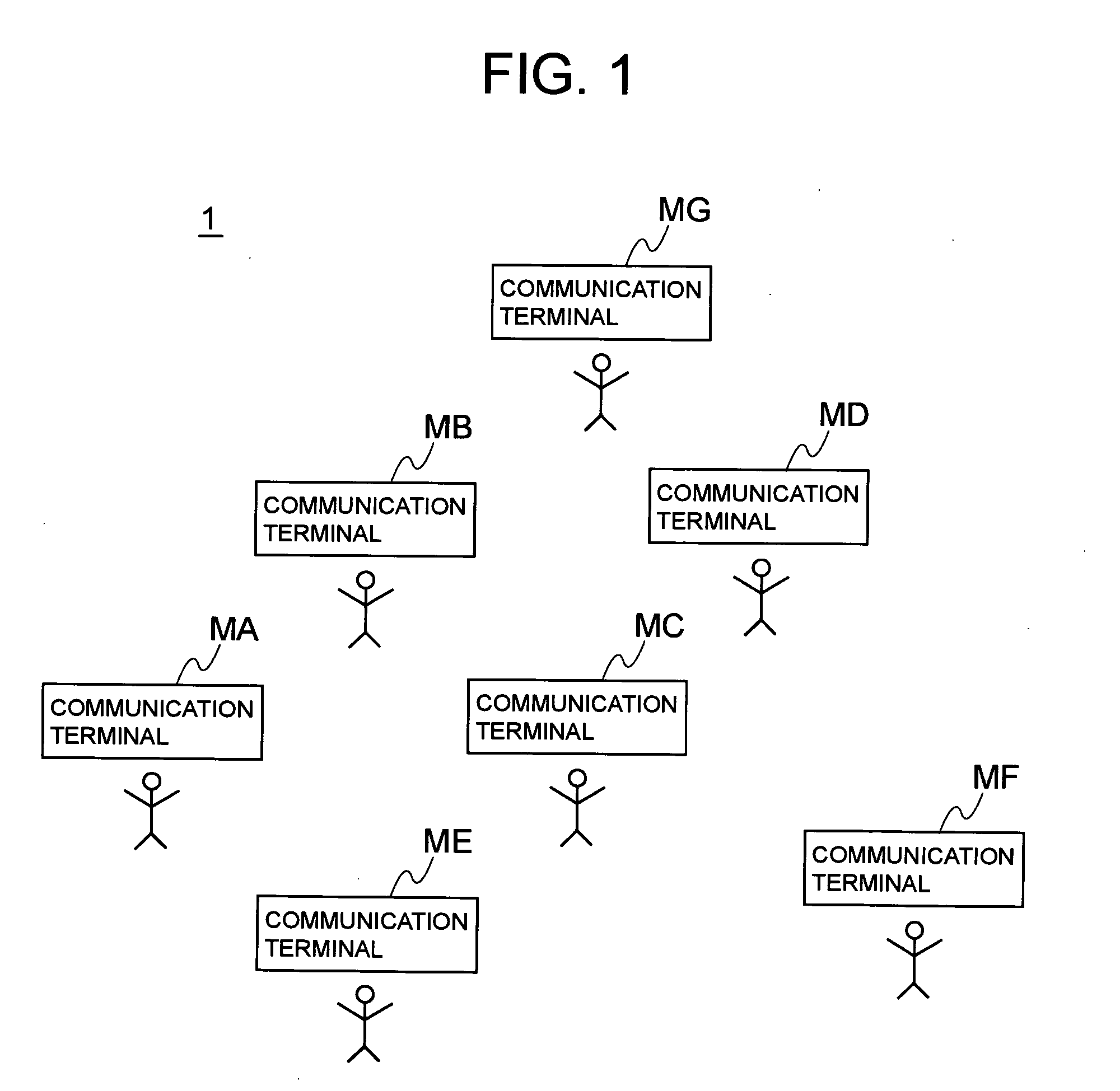
[0020]FIG. 1 is a configuration diagram showing the entire configuration of a radio communication system according to the present embodiment. Radio communication terminals MA to MG are each a terminal such as a mobile phone, a PDA, or a portable game terminal which can exchange data with an adjacent radio communication terminal and establish a so-called ad hoc network. The user of each of the radio communication terminals MA to MG carries it and moves around or stays in a place such as a residential area, an office, or commercial facilities.

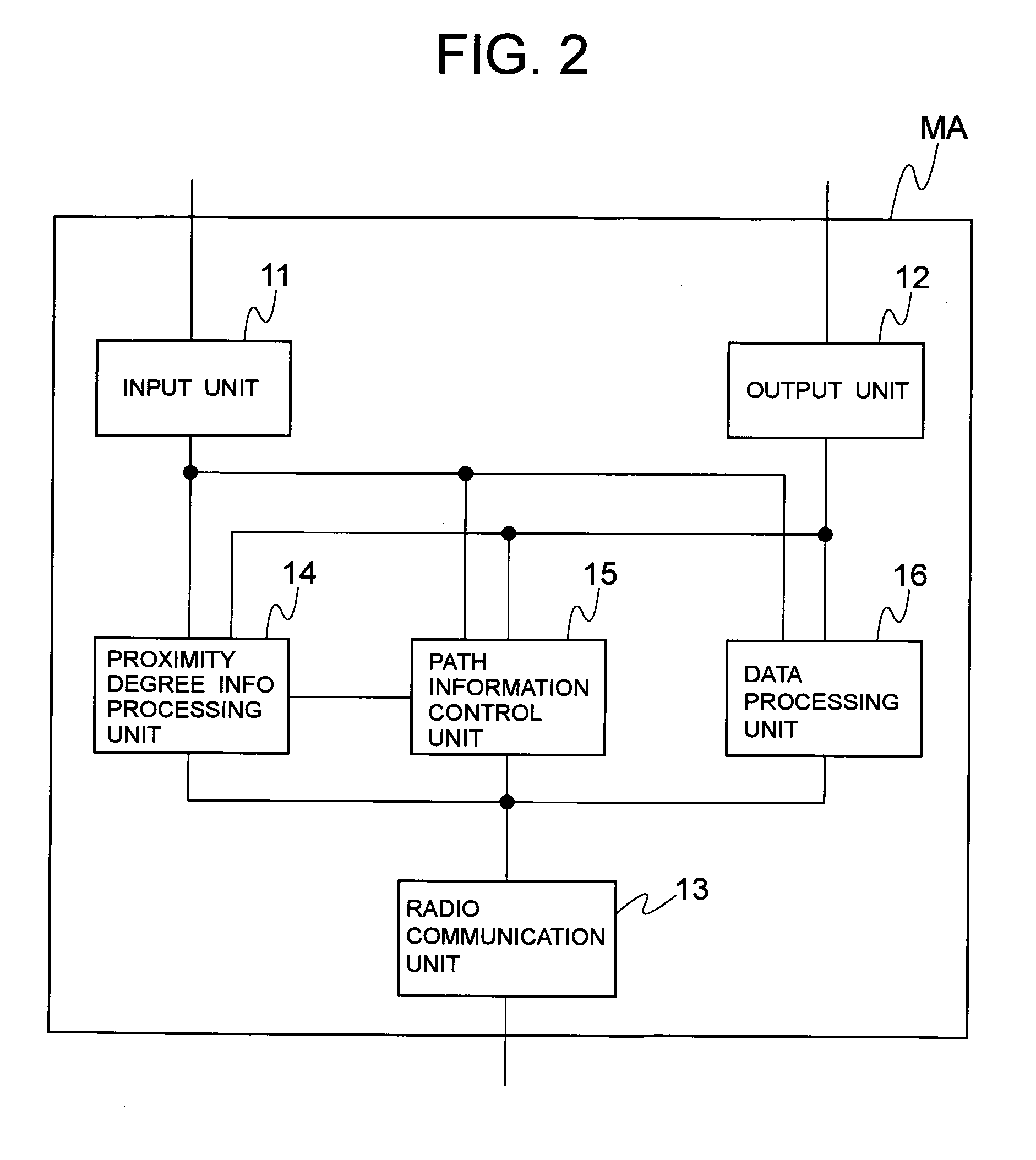
[0021]FIG. 2 is a block diagram showing the configuration of the radio communication terminal MA. The radio communication terminal MA comprises an input unit 11, an output unit 12, a radio communication unit 13, a proximity degree information processing unit 14, a path information control unit 15, and a data processing unit 16.

[0022]The input unit 11 is an input device to accept terminal operation input or data input from a user, such as a keyboa...

second embodiment

[0059]The block diagram of a second embodiment is the same as the block diagram (FIG. 2) of the first embodiment. Part in which it differs from the first embodiment will mainly be described below. In the second embodiment, control below is added to the updating of the data delivery path information in the path information control unit 15 of the block diagram of the first embodiment.

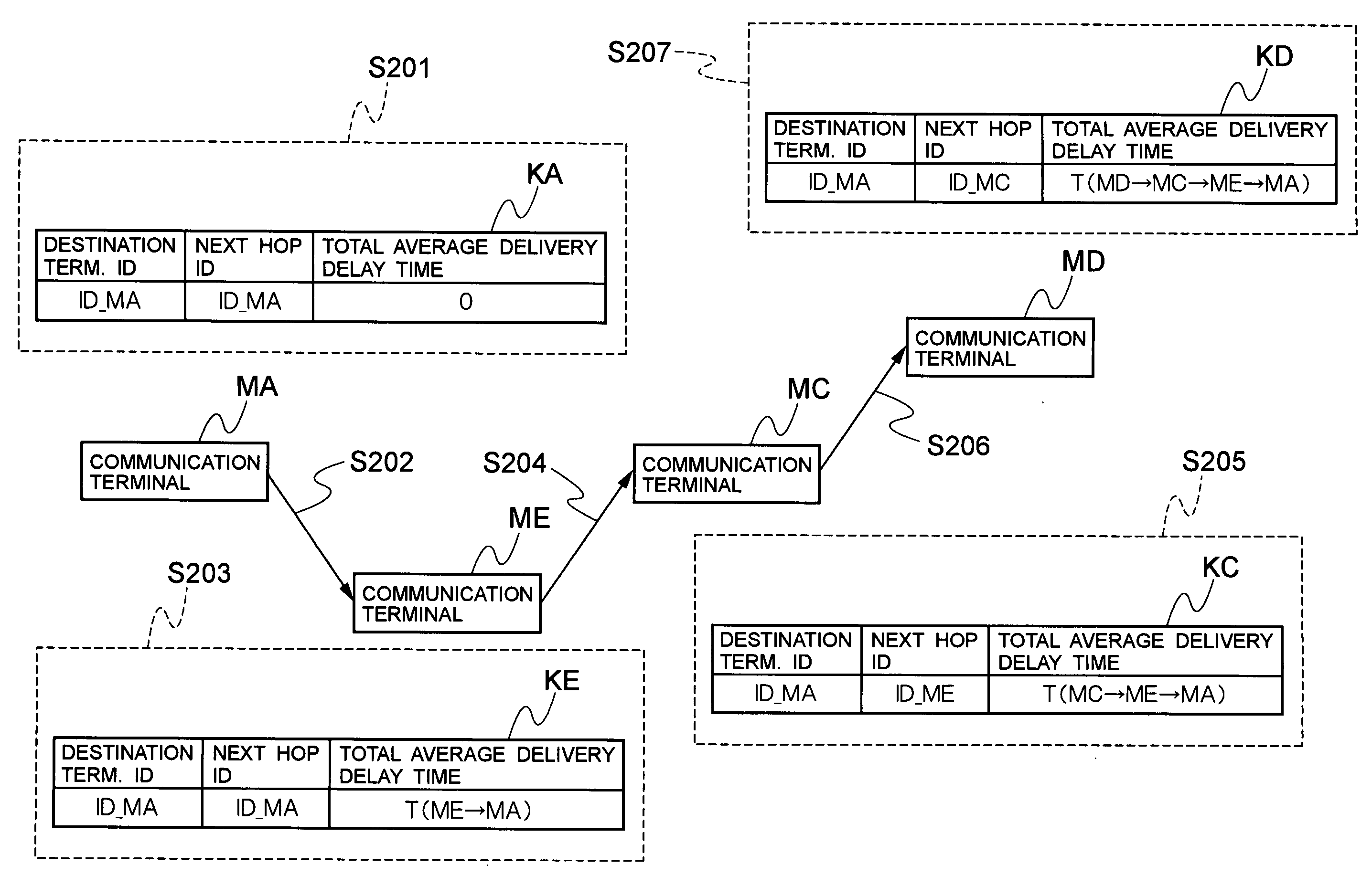
[0060]FIG. 9 is a diagram showing a relationship between elapsed time and the transmission / reception of the data delivery path information. As described in the first embodiment, the radio communication terminal MA transmits the data delivery path information each time a predetermined condition is satisfied such as the one that the reception interval of beacons from a radio communication terminal is at or above a predetermined transmission threshold value Tth_s. At this time, the radio communication terminal MC may receive a plurality of data delivery path information via a plurality of different paths. Fo...


PUM


Abstract

A radio communication system in which radio communication terminals can efficiently transmit and receive data with each other suppressing the amount of data held by each of them. Each radio communication terminal can calculate an average delivery delay time of deliver data based on the degree of proximity to an adjacent radio communication terminal and transmit data delivery path information containing this and, for each data delivery path information received from another radio communication terminal, calculate a total average delivery delay time for delivery to a destination radio communication terminal based on the average delivery delay time contained in the data delivery path information and the average delivery delay time calculated by itself and, in response to the arrival of a data delivery time, transmit deliver data toward the destination radio communication terminal via the delivery path associated with the smallest total average delivery delay time.

Description

BACKGROUND OF THE INVENTION[0001]1. Field of the Invention[0002]The present invention relates to a radio communication system including a plurality of radio communication terminals each implementing radio communication functions.[0003]2. Description of the Related Art[0004]In these years, attempts have been made to establish a so-called ad hoc network over which data is exchanged between terminals able to radio-communicate such as personal computers, PDAs, or mobile phones directly, not via a base station. Since a base station or an access point is unnecessary, the ad hoc network can be established inexpensively and is perceived as effective means for establishing a network within a limited area. However, with ad hoc networks of which radio communication terminals move over a wide area, there is the following problem: since radio communication terminals can move freely, the radio communication terminals may become far apart, in which case the link between the radio communication ter...

Claims


Application Information

Patent Timeline
IPC IPC(8): H04W28/02
CPCH04L45/121H04W88/04H04W40/02H04L45/70
Inventor SEKINE, MASATOSHI
Owner OKI ELECTRIC IND CO LTD
Why Eureka
Try Eureka