Cooperative Wireless Networks

a wireless network and cooperative technology, applied in the field of antennaarray processing and adhoc networking, can solve the problems of insufficient spatial reuse, inability to fully realize the effect of increasing spatial reuse, and the inability to translate into greater throughpu

Inactive Publication Date: 2009-12-17
GENGHISCOMM HLDG
View PDF57 Cites 101 Cited by
  • Summary
  • Abstract
  • Description
  • Claims
  • Application Information

AI Technical Summary

Benefits of technology

[0014]Some of the exemplary embodiments of the present invention are summarized as follows. Embodiments of the invention include beam-forming systems configured to enable spatially separated wireless terminals (WTs) to perform beam-forming operations in a wireless wide area network (WWAN). A wireless local area network (WLAN) couples together the WTs, which

Problems solved by technology

Although peer-to-peer networking shows some promise, there are significant drawbacks that prevent conventional peer-to-peer networks from being a technically and commercially viable solution.
Recent analyses of multi-hop networks compared to cellular networks have indicated that the spatial reuse improvement in the peer-to-peer network model does not translate into greater throughput.
Thus, any increase in spatial reuse cannot be fully realized as the channel around the base-station becomes a bottleneck and has to be shared by all the flows in the network.
Cellular proto

Method used


Image

  • Cooperative Wireless Networks
  • Cooperative Wireless Networks
  • Cooperative Wireless Networks

Examples


Embodiment Construction

[0058]While the invention is susceptible to various modifications and alternative forms, specific embodiments thereof are shown by way of example in the drawings and are herein described in detail. It should be understood, however, that the exemplary embodiments are not intended to limit the invention to the particular forms disclosed. Instead, the invention is to cover all modifications, equivalents, and alternatives falling within the spirit and scope of the invention as defined by the claims.

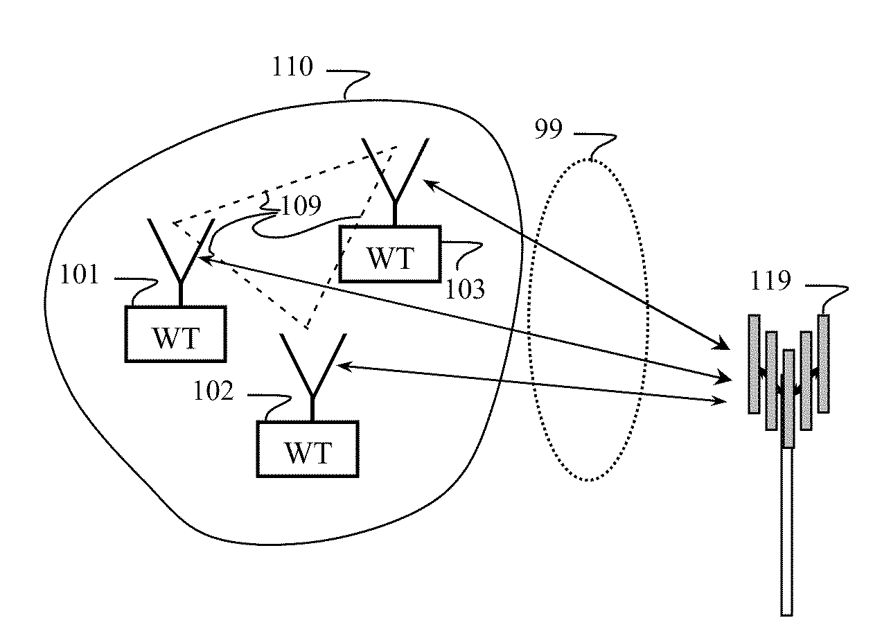
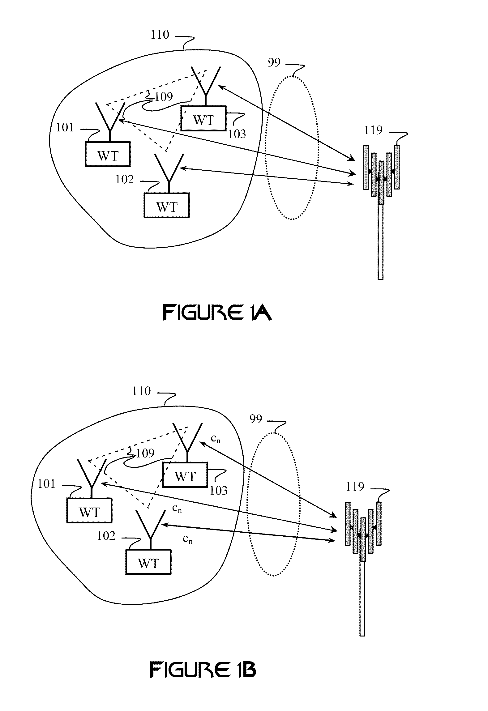
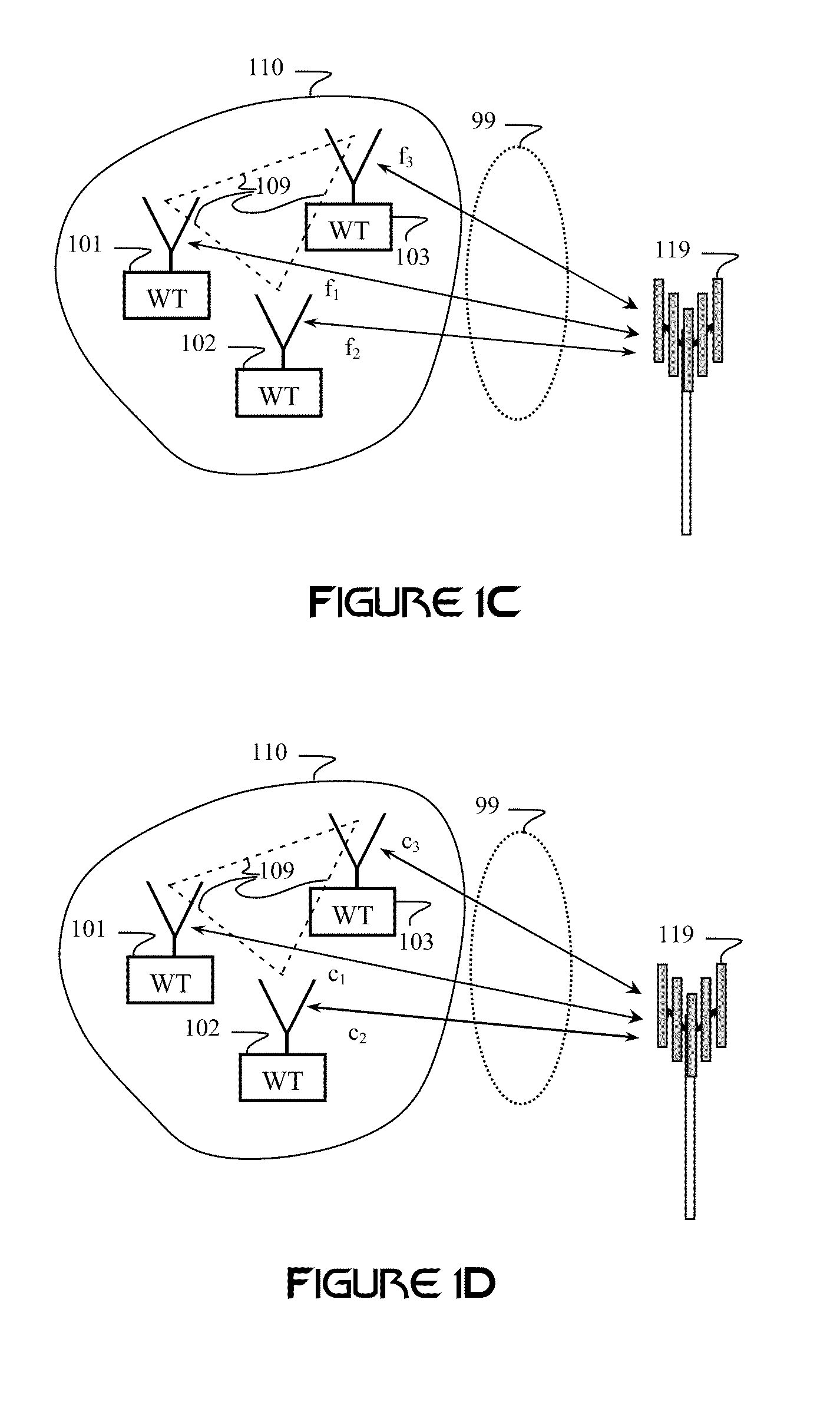
[0059]FIG. 1A illustrates how some embodiments of the invention may be employed in a cellular network. Each wireless terminal (WT) of a plurality of WTs 101-103 is in radio contact with at least one wireless wide area network (WWAN) terminal, which may also be referred to as a WWAN node, such as cellular base station 119. The cellular base station 119 may include one or more antennas (e.g., an antenna array). WWAN signals transmitted between the base station 119 and the WTs 101-103 propagate ...


PUM


Abstract

A wireless local area network (WLAN) communicatively couples together a group of mobile wireless terminals configured to operate in a wireless wide area network (WWAN). A network-management operator processes WWAN-control messages used by the mobile wireless terminals and the WWAN. One or more of the mobile wireless terminals may function as the network-management operator.

Description

RELATED APPLICATIONS[0001]This application is a Divisional of U.S. patent application Ser. No. 11 / 187,107, entitled “Cooperative Beam-Forming in Wireless Networks,” filed on Jul. 22, 2005, which claims priority to Provisional Appl. No. 60 / 598,187, filed Aug. 2, 2004 and is a Continuation In Part of U.S. patent application Ser. No. 10 / 145,854, entitled “Carrier Interferometry Networks,” which was filed on May 14, 2002, which was a Continuation In Part of U.S. patent application Ser. No. 09 / 718,851, entitled “Multiple Input, Multiple Output Carrier Interferometry Architecture,” filed on Nov. 22, 2000.BACKGROUND OF THE INVENTION[0002]I. Field of the Invention[0003]The present invention relates generally to antenna-array processing and ad-hoc networking, and particularly to providing cooperative signal processing between a plurality of wireless terminal devices, such as to improve network access.[0004]II. Description of the Related Art[0005]Wireless data service is an emerging market wi...

Claims


Application Information

Patent Timeline
IPC IPC(8): H04W84/12H04L45/24H04W72/04H04W84/18
CPCH04B7/026H04L5/0073H04J13/004H04J13/12H04L5/0021H04L27/2601H04L27/2602H04L27/2614H04L45/24H04L47/10H04W72/046H04W84/18H04B7/0456H04B7/0452H04L5/0035H04L5/0037H04J13/0003H04B1/0003H04L5/0023H04L27/26526H04L27/26534H04L5/0007H04B7/024H04L27/2636H04L27/2646H04B7/0697H04L27/01H04L27/148H04L27/2647
Inventor SHATTI, STEVE
Owner GENGHISCOMM HLDG
Why Eureka
Try Eureka