Perpendicular magnetic recording disk and method of manufacturing the same

a magnetic recording disk and perpendicular technology, applied in the direction of magnetic recording, magnetic recording heads, instruments, etc., can solve the problems of loss of recorded signals, impediment to the increase of the recording density of the magnetic recording disk, degraded thermal stability of recorded signals, etc., to achieve high coercive force (hc), low noise characteristics, and high s/n ratio

Inactive Publication Date: 2009-12-17
WD MEDIA SINGAPORE PTE
View PDF5 Cites 73 Cited by
  • Summary
  • Abstract
  • Description
  • Claims
  • Application Information

AI Technical Summary

Benefits of technology

[0021]According to this invention, it is possible to achieve both segregation of a nonmagnetic substance and high perpendicular magnetic anisotropy to

Problems solved by technology

However, in the case of conventionally commercialized magnetic disks of the in-plane magnetic recording type (also called the longitudinal magnetic recording type or the horizontal magnetic recording type), as a result of the reduction in size of magnetic crystal grains, there h

Method used


Image

  • Perpendicular magnetic recording disk and method of manufacturing the same
  • Perpendicular magnetic recording disk and method of manufacturing the same
  • Perpendicular magnetic recording disk and method of manufacturing the same

Examples


first embodiment

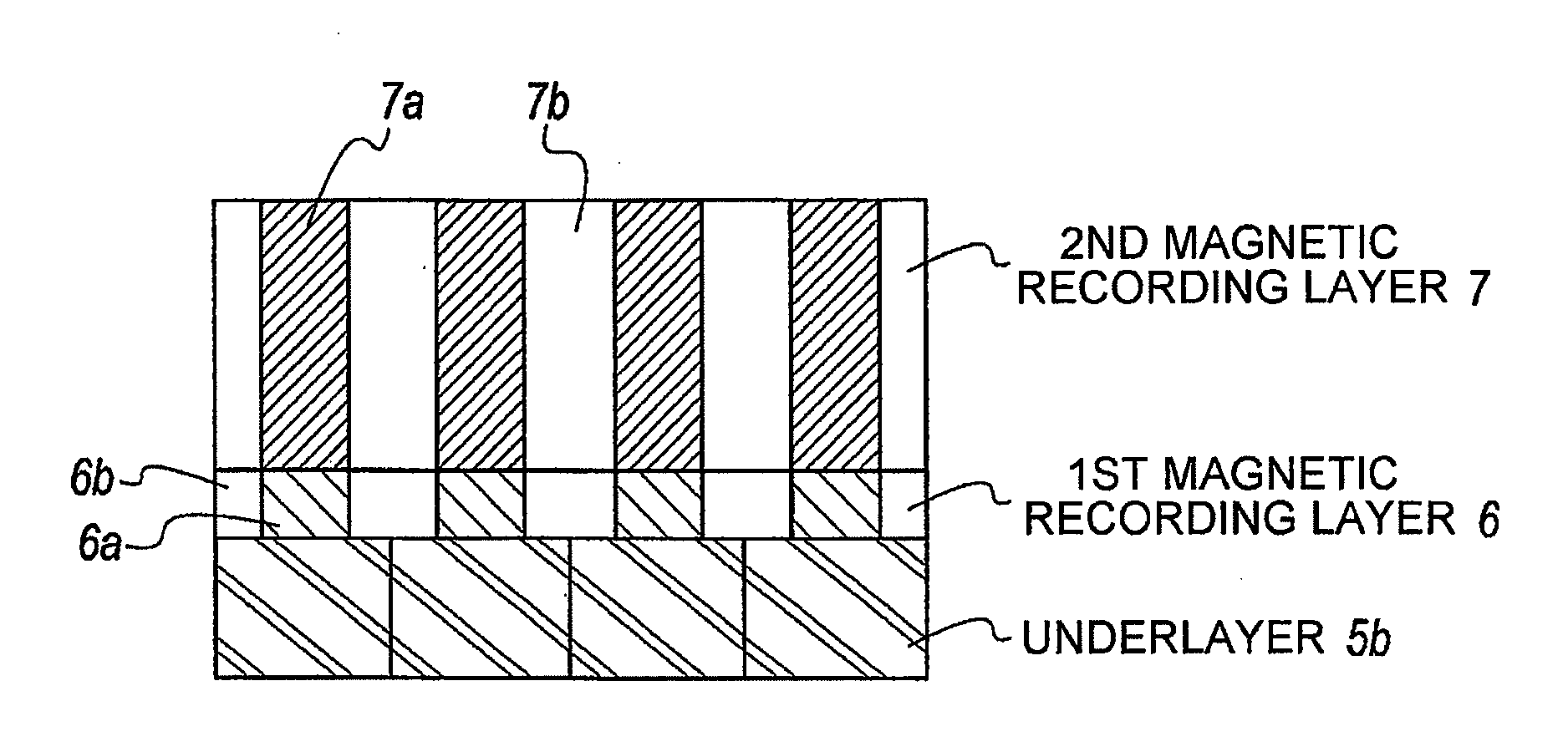
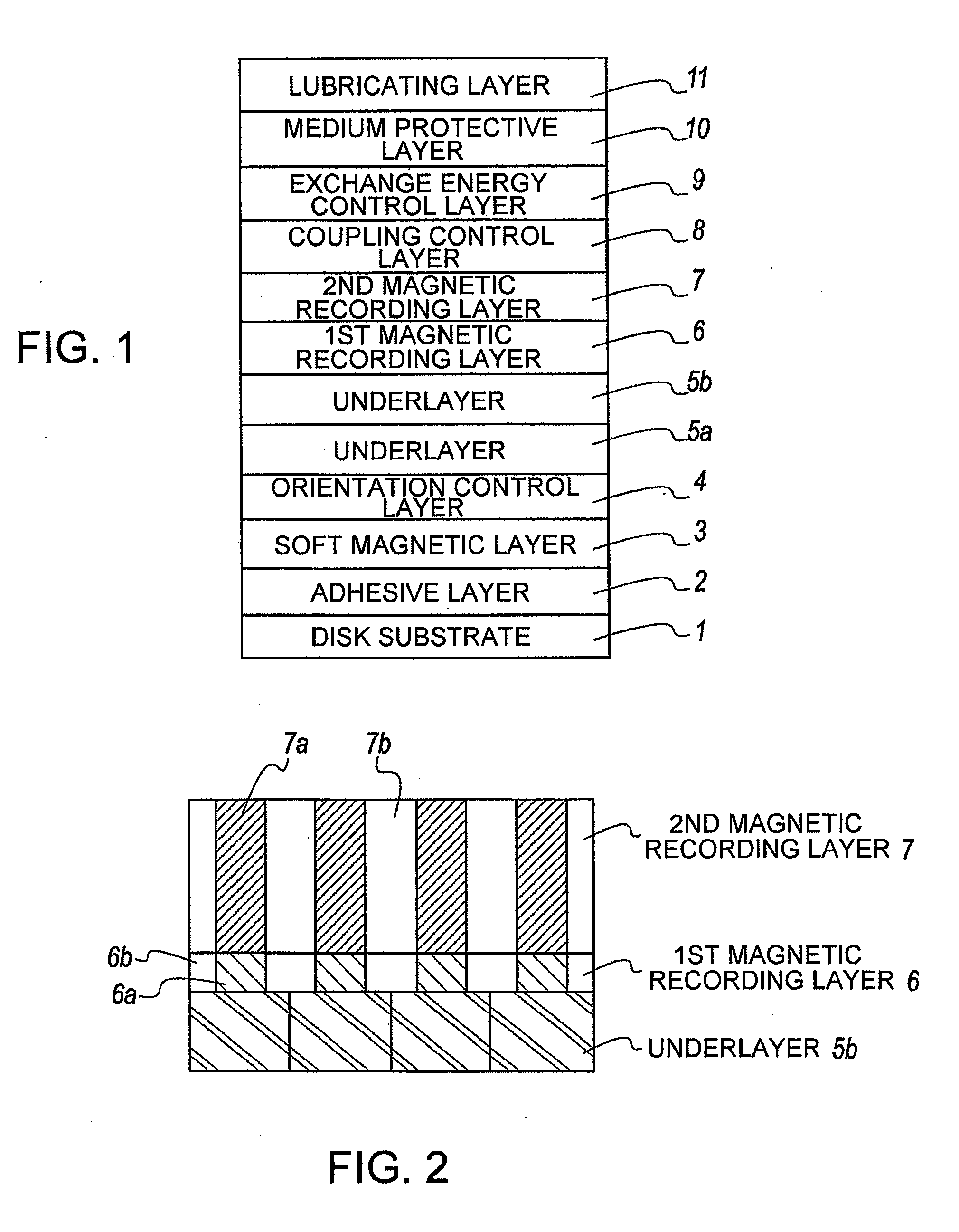
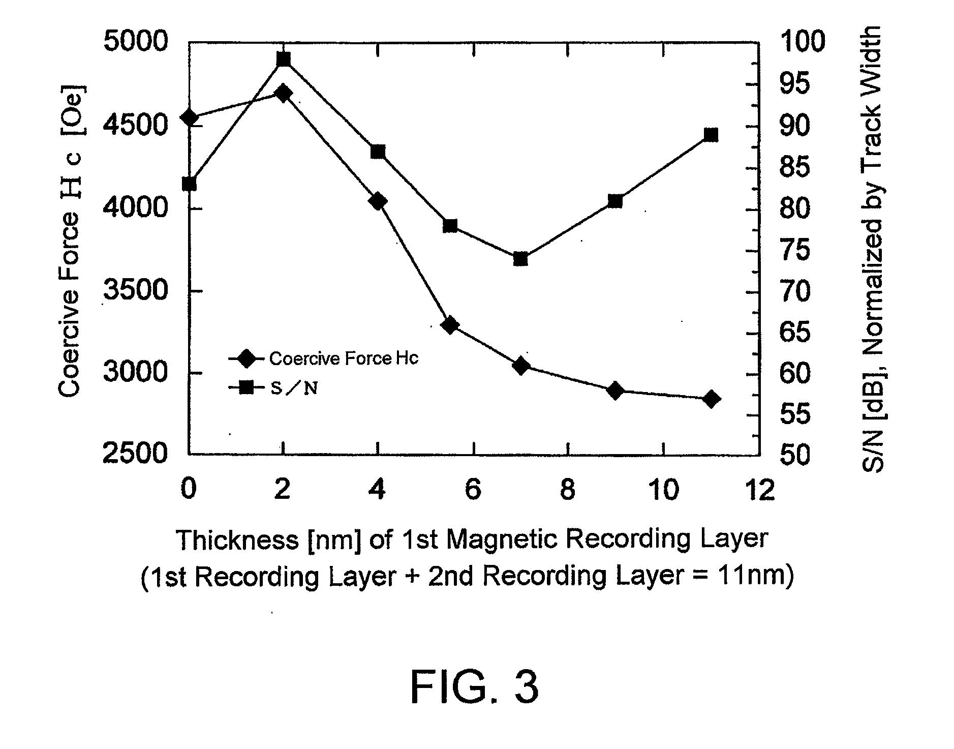
[0052]A first embodiment of a perpendicular magnetic recording medium according to this invention will be described with reference to the drawings. FIG. 1 is a diagram for explaining the configuration of the perpendicular magnetic recording medium according to the first embodiment, FIG. 2 is an exemplary diagram for explaining the vicinity of magnetic recording layers, and FIG. 3 is a diagram showing the relationship between coercive force and noise when the thicknesses of the first and second magnetic recording layers are changed. Numerical values given in the following embodiment are only examples for facilitating the understanding of this invention and are not intended to limit this invention unless otherwise stated.

[0053]The perpendicular magnetic recording medium shown in FIG. 1 comprises a disk substrate 1, an adhesive layer 2, a soft magnetic layer 3, an orientation control layer 4, an underlayer 5a, an underlayer 5b, a first magnetic recording layer 6, a second magnetic reco...

second embodiment

[0078]A second embodiment of a perpendicular magnetic recording medium according to this invention will be described with reference to the drawings. FIG. 4 is a diagram for explaining the configuration of the perpendicular magnetic recording medium according to the second embodiment and FIG. 5 is a diagram showing the relationship between coercive force and noise when the thicknesses of first and second magnetic recording layers according to the second embodiment are changed. The same symbols are assigned to those portions of which description overlaps that of the foregoing first embodiment, thereby omitting explanation thereof.

[0079]The perpendicular magnetic recording medium shown in FIG. 4 comprises a disk substrate 1, a soft magnetic layer 23, an orientation control layer 24, an underlayer 5, an onset layer 26, a first magnetic recording layer 27, a second magnetic recording layer 28, a medium protective layer 10, and a lubricating layer 11.

[0080]The soft magnetic layer 23 is fo...


PUM


Abstract

[Object] To achieve a high coercive force (Hc) and low-noise characteristics (high S/N ratio) through realization of both segregation of SiO2 and high perpendicular magnetic anisotropy by providing a two-layer structure having magnetic recording layers with different properties.
[Solution] A magnetic disk for use in perpendicular magnetic recording, having at least an underlayer 5, a first magnetic recording layer 6, and a second magnetic recording layer 7 on a substrate in this order. The first magnetic recording layer 6 and the second magnetic recording layer 7 are each a ferromagnetic layer of a granular structure containing a nonmagnetic substance forming grain boundary portions between crystal grains containing at least Co (cobalt). Given that the content of the nonmagnetic substance in the first magnetic recording layer 6 is A mol % and the content of the nonmagnetic substance in the second magnetic recording layer 7 is B mol %, A>B.

Description

TECHNICAL FIELD[0001]This invention relates to a perpendicular magnetic recording medium adapted to be mounted in a perpendicular magnetic recording type HDD (hard disk drive) or the like.BACKGROUND ART[0002]Various information recording techniques have been developed following the increase in volume of information processing in recent years. Particularly, the areal recording density of HDDs (hard disk drives) using the magnetic recording technique has been increasing at an annual rate of about 100%. Recently, the information recording capacity exceeding 100 GB has been required per 2.5-inch magnetic disk adapted for use in a HDD or the like. In order to satisfy such a requirement, it is necessary to realize an information recording density exceeding 200 Gbits / inch2. In order to achieve the high recording density in a magnetic disk for use in a HDD or the like, it is necessary to reduce the size of magnetic crystal grains forming a magnetic recording layer serving to record informat...

Claims


Application Information

Patent Timeline
IPC IPC(8): G11B5/66G11B5/33B05D5/12
CPCG11B5/65G11B5/7325G11B5/667G11B5/66G11B5/73921G11B5/7368G11B5/7369G11B5/737G11B5/672
Inventor ONOUE, TAKAHIROKIM, KONGSONOBE, YOSHIAKITAKASU, CHIKARA
Owner WD MEDIA SINGAPORE PTE
Why Eureka
Try Eureka