
Fuel cell with passive operation

Inactive Publication Date: 2009-12-17
BABCOCK BRIAN DAVID
View PDF12 Cites 2 Cited by
  • Summary
  • Abstract
  • Description
  • Claims
  • Application Information

AI Technical Summary

Benefits of technology

[0019]The invention can be used with multiple types of fuel cells. Most fuel cells will benefit from one or more aspects of this invention. Because fuel cells rely on reactions at the anode and cathode sites, all fuel cells have a ne

Problems solved by technology

Hydrogen, however, is not so readily available and specific measures must be taken to ensure its provision to the fuel cell.
However, as can readily be appreciated, the reforming or processing of the organic fuel into hydrogen gas requires special equipment (adding weight and size to the system) and itself requires the expenditure of energy.
Unfortunately, however, the proton exchange membrane typically used in a liquid feed system is rather permeable to the organic fuel.
As a result, a substantial portion of the organic fuel delivered to the anode has a tendency to permeate through the proton exchange membrane, instead of being oxidized at the anode.
Moreover, much of the fuel that transits the proton exchange membrane is chemically reacted at the cathode and, therefore, cannot be collected and recirculated to the anode.
In addition, this problem of cross-over is exacerbated if the concentration of organic fuel in the aqueous solution is increased beyond the approximately 3-5 wt % described above since the permeability of the proton exchange membrane increases exponentially as the organic fuel concentration increases.
However, as can be appreciated, the required quantities of water can be heavy and space-consuming and can pose a problem to the portability of the system.
Another complication resulting from the high concentration of water present in the aqueous solution is that a considerable amount of water delivered to the anode also permeates through the proton exchange membrane to the cathode.
This excess water arriving at the cathode limits the accessibility of the cathode to gaseous oxygen, which must be reduced at the cathode to complement the oxidation of the fuel at the anode.
As can readily be appreciated, flooding adversely affects fuel cell performance.
However, some of the disadvantages of a typical vapor feed system are that the system must be operated at above 100° C. in order to prevent condensation of the fuel / water mixture at the anode.
As can be appreciated, the foregoing conditions require the use of specialized equipment that is space-consuming and that requires the expenditure of energy for its own operation.
Moreover, due to the amount of heat that is generated as an unwanted byproduct in the fuel cell, a vapor feed system must also include a cooling assembly, typically in the form of coolant plates and a circulating coolant, to keep the fuel cell from getting too hot.
Such a cooling assembly can add considerable weight and volume to the system, especially if a multi-cell stack is used, since one cooling plate is needed for every 2-5 active cells.

Method used


Image

  • Fuel cell with passive operation
  • Fuel cell with passive operation
  • Fuel cell with passive operation

Examples


Embodiment Construction

[0031]A fuel cell stack design can be assembled by combining specialty media layers with the Membrane Electrode Assembly (MEA) materials to produce a thin, low-cost fuel cell suitable for portable applications. The media layers provide the following functions in the fuel cell:

[0032]Fuel delivery means

[0033]Gas-liquid separation at the anode site

[0034]Water management and oxygen delivery at the cathode site.

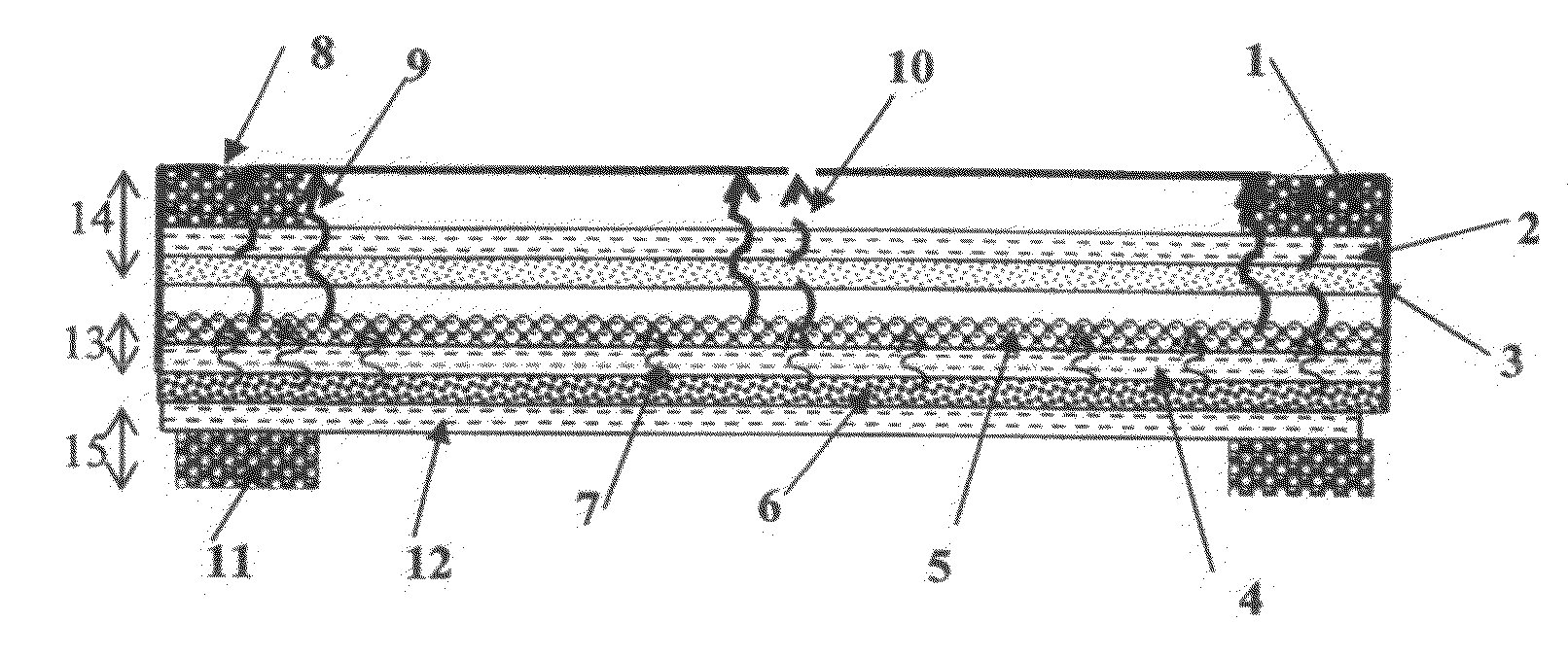
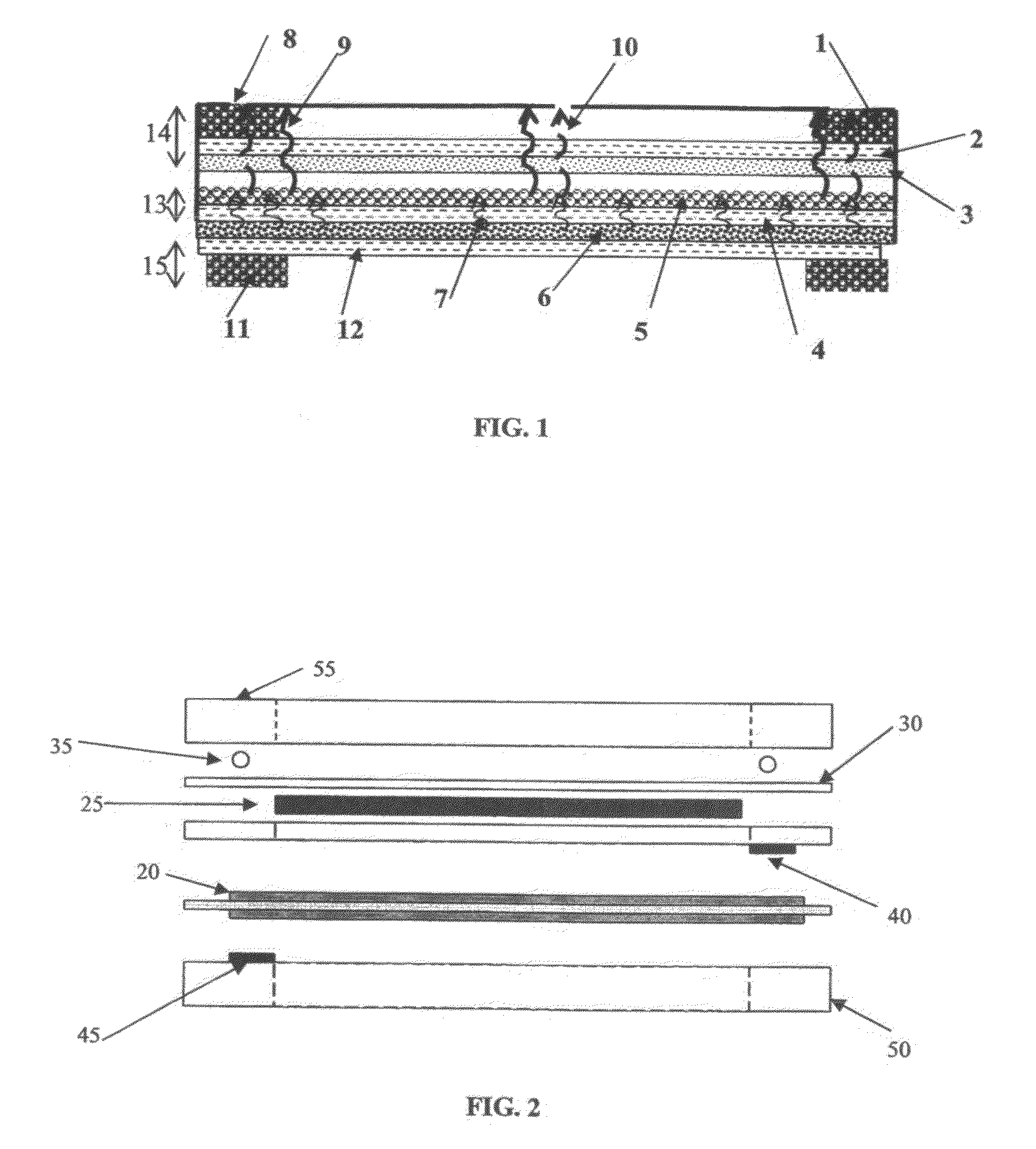
[0035]Combining all three components (fuel delivery, gas-liquid separator (GLS), and liquid management) with a membrane electrode assembly (MEA) containing anode and cathode catalysts on either side results in an operational fuel cell stack. FIG. 1 shows an embodiment of the fuel cell design that gives additional detail on each layer of the stack components.

[0036]In FIG. 1, fuel is stored in the absorbent layer 5 of the fuel delivery material and is transferred by the wicking layer 4 of the fuel delivery material to the anode side of the MEA 6. The absorbent layer 5 and the wickin...


PUM


Abstract

A fuel cell comprising an anode and cathode, fuel delivery means comprising a superabsorbent nonwoven absorbent media in fluid contact with a wicking material, gas-liquid separation means, and water management means. In one embodiment, the fuel cell also uses a microporous membrane, a wicking material, and an absorbent material to provide for gas-liquid separation, and a wicking material and absorbent material to provide for liquid management means at the cathode. In some embodiments, the combination of materials provides the advantage of passive operation and orientation independence for the fuel cell.

Description

CROSS-REFERENCES TO RELATED APPLICATIONS[0001]This application claims the benefit of U.S. Provisional Patent Application Ser. No. 61 / 131,285, entitled “Fuel Cell with Passive Operation,” filed Jun. 6, 2008, the contents of which is herein incorporated by reference in its entirety.STATEMENT REGARDING FEDERALLY SPONSORED RESEARCH OR DEVELOPMENT[0002]Not ApplicablePARTIES TO A JOINT RESEARCH AGREEMENT[0003]Not ApplicableFIELD OF THE INVENTION[0004]This invention is an improved fuel cell design that uses media layers to deliver fuel to the anode reaction site, provide gas-liquid separation at the anode site, and manages liquid production at the cathode site. The fuel cell comprises a superabsorbent material with a wicking material to deliver fuel, and combinations of microporous membranes, wicking materials, and absorbent materials together to separate gas and vapor from the liquid fuel and transfer or store the condensed liquid from the fuel cell. The fuel cell offers the advantages of...

Claims


Application Information

Patent Timeline
IPC IPC(8): H01M2/00
CPCH01M8/04149Y02E60/521H01M8/1009H01M8/04171Y02E60/50
Inventor BABCOCK, BRIAN DAVID
Owner BABCOCK BRIAN DAVID
Learn More