
Walking assist device

a technology of assist device and walking aid, which is applied in the direction of chiropractic device, program-controlled manipulator, physical therapy, etc., can solve the problems of reducing the measuring accuracy of the supporting force required for controlling the lifting force, the user's lifting force to be applied, and the difficulty of high resolution and high accuracy of supporting force measurement, so as to prevent the user from feeling uncomfortabl

Active Publication Date: 2009-12-17
HONDA MOTOR CO LTD
View PDF7 Cites 8 Cited by
  • Summary
  • Abstract
  • Description
  • Claims
  • Application Information

AI Technical Summary

Benefits of technology

[0015]In this case, the connecting rod does not need to transmit such a large translational force that can support the weight of the entire walking assist device. Therefore, the range of values of the rod transmitting force is relatively small. Moreover, since the magnitude of the rod transmitting force is not so large, the connecting rod is less apt to be deformed. Consequently, the connecting rod is less apt to be subjected to a force in directions other than the longitudinal direction of the connecting rod, such as in the transverse (shear) direction of the connecting rod. Further, since the connecting rod is provided along the thigh frame of each leg link, the connecting rod is less likely to come into contact with other objects while the user is walking in comparison with the end side of each leg link (the lower end side of the crus frame).
[0017]Moreover, in the first aspect of the invention, the actuator control means feedback-controls the driving force of the rotary actuator so that the controlled variable coincides with the controlled variable desired value which is a desired value of the controlled variable requested to control the lifting force to a desired lifting force. This enables an actual controlled variable to coincide with the controlled variable desired value accurately and stably. In this case, the accurate and stable coincidence between the controlled variable and the controlled variable desired value means that it is consequently possible to stably control an actual supporting force acting on each leg link from the floor side to an appropriate supporting force (the supporting force corresponding to the controlled variable desired value) enabling the desired lifting force to be applied to the user from the lifting force transmitting portion.
[0020]Specifically, the stain gauge constituting the strain gauge force sensor generally has high sensitivity only in a particular direction. Therefore, the use of the strain gauge force sensor enables more accurate measurement of the rod transmitting force in the longitudinal direction of the connecting rod.
[0022]Specifically, in order to apply an upward lifting force to the user from the lifting force transmitting portion, it is necessary to apply the driving torque, which biases the leg link in the stretching direction, to the third joint of the leg link connected to the foot attachment portion in contact with the ground. The rod transmitting force is largest at the time of applying the driving torque. In this case, according to the third aspect of the invention, the rod transmitting force in biasing the leg link in the stretching direction is a tractive force. Therefore, the rod transmitting force effectively prevents an occurrence of deformation such as buckling of the connecting rod. Consequently, the walking assist device is capable of measuring the rod transmitting force more accurately.
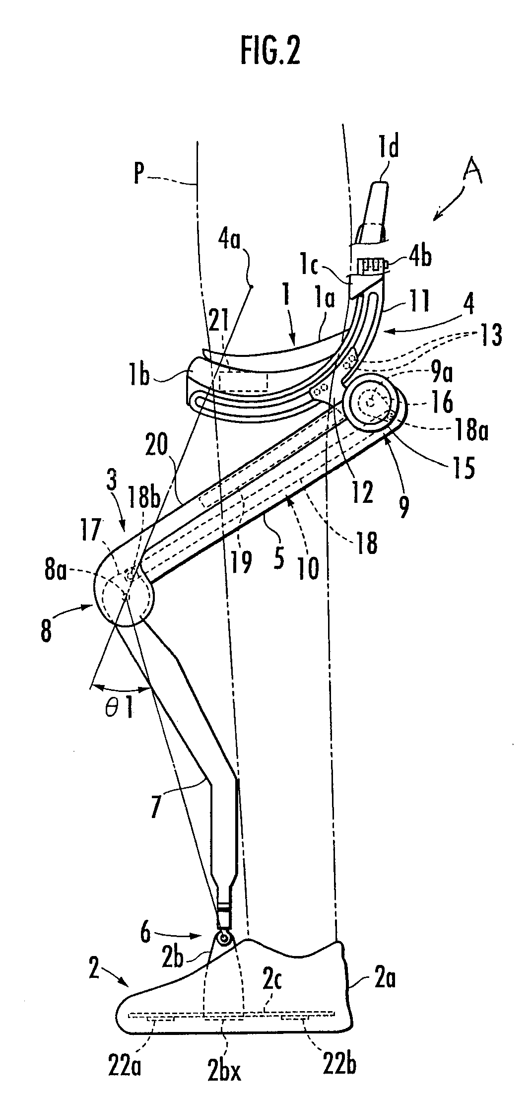
[0024]According to the fourth aspect of the invention, in order to control the lifting force to the desired lifting force, the desired supporting force setting means sets the desired supporting force which is a desired value of the supporting force to be applied to each leg link from the floor side. In addition, on the assumption that the desired supporting force is applied to the leg link from the floor side, the controlled variable desired value, which is requested to provide the third joint of the leg link with a torque balanced with a moment applied to the third joint of the leg link by the desired supporting force, is determined on the basis of the set desired supporting force and the value of the displacement angle of the third joint measured by the joint angle measuring means. Therefore, it is possible to easily determine a controlled variable desired value appropriate for controlling the lifting force to the desired lifting force. The reason for requiring the measured value of the displacement angle of the third joint in addition to the desired supporting force in order to determine the controlled variable desired value is that the moment acting on the third joint of the leg link by the desired supporting force varies according to the displacement angle of the third joint of the leg link.
[0026]According to the fifth aspect of the invention, on the assumption that the desired supporting force set by the desired supporting force setting means is applied to the leg link from the floor side, the basic value of the controlled variable desired value is determined with the basic value defined as a value of the controlled variable requested to provide the third joint of the leg link with a torque balanced with the moment applied to the third joint of the leg link by the desired supporting force. Moreover, in the fifth aspect of the invention, an additional correction amount including a correction amount of the basic value is determined on the basis of the measured value of the displacement angle of the third joint, where the additional correction amount is requested to provide the third joint of the leg link with a torque against at least one of a resistance force generated at the third joint due to a frictional force at the third joint of the leg link, a resistance force generated at the third joint of the leg link due to an inertial force caused by a motion of the part on the foot attachment portion side from the third joint of each leg link, and a resistance force generated at the third joint of the leg link due to a gravity acting on the part on the foot attachment portion side from the third joint of each leg link. The controlled variable desired value is determined by correcting the basic value with the additional correction amount. Further, the actuator control means feedback-controls the driving force of the rotary actuator so that the controlled variable desired value determined in this manner coincides with an actual controlled variable. This enables the compensation for the effect of a resistance force caused by at least one of the frictional force, the inertial force, and the gravity described above. Consequently, it is possible to prevent the user from feeling uncomfortable in moving the foot attachment portion in the air.

Problems solved by technology

This causes a lifting force to be applied to the user from the seat member and consequently the walking assist device bears a part of the weight of the user.
The above conventional walking assist device, however, controls the electric motor in such a way as to directly achieve matching between the desired value and the value of the supporting force measured from the output of the supporting force measurement force sensor interposed between the crus frame and the second joint of each leg link and therefore has a problem described below.
Therefore, it is difficult to measure the supporting force with high resolution and high accuracy.
Therefore, an interference of the forces in the lateral direction easily decreases the measuring accuracy of the supporting forces required for controlling the lifting force (the supporting forces substantially in the vertical direction).
Further, the lower ends of the leg links are widely movable relative to the seat member and therefore often come into contact with other objects.
These contacts are also causes of decreasing the measurement accuracy of the supporting forces.
The decrease in the measurement accuracy of the supporting forces could lead to inappropriate driving torques, which are applied to the third joints of the leg links by the electric motors, for applying the desired lifting force to the user from the seat member.
In another case, the decrease in the measurement accuracy could lead to a difference between the actual lifting force and the desired lifting force, which gives discomfort to the user.

Method used


Image

  • Walking assist device
  • Walking assist device
  • Walking assist device

Examples


Embodiment Construction

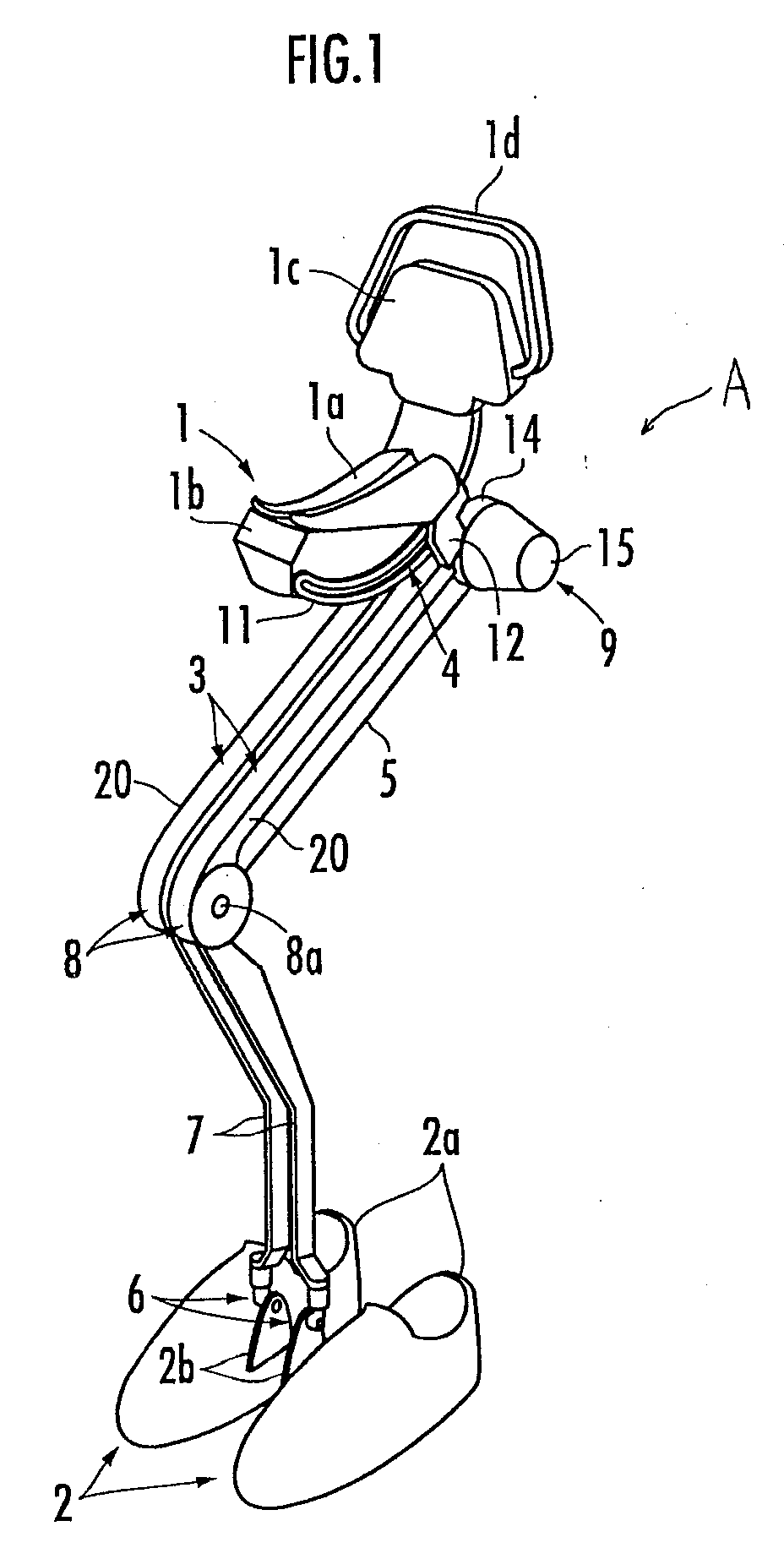
[0038]An embodiment of the present invention will be described in detail hereinafter. First, a mechanical configuration of a walking assist device of this embodiment is described with reference to FIGS. 1 to 4.

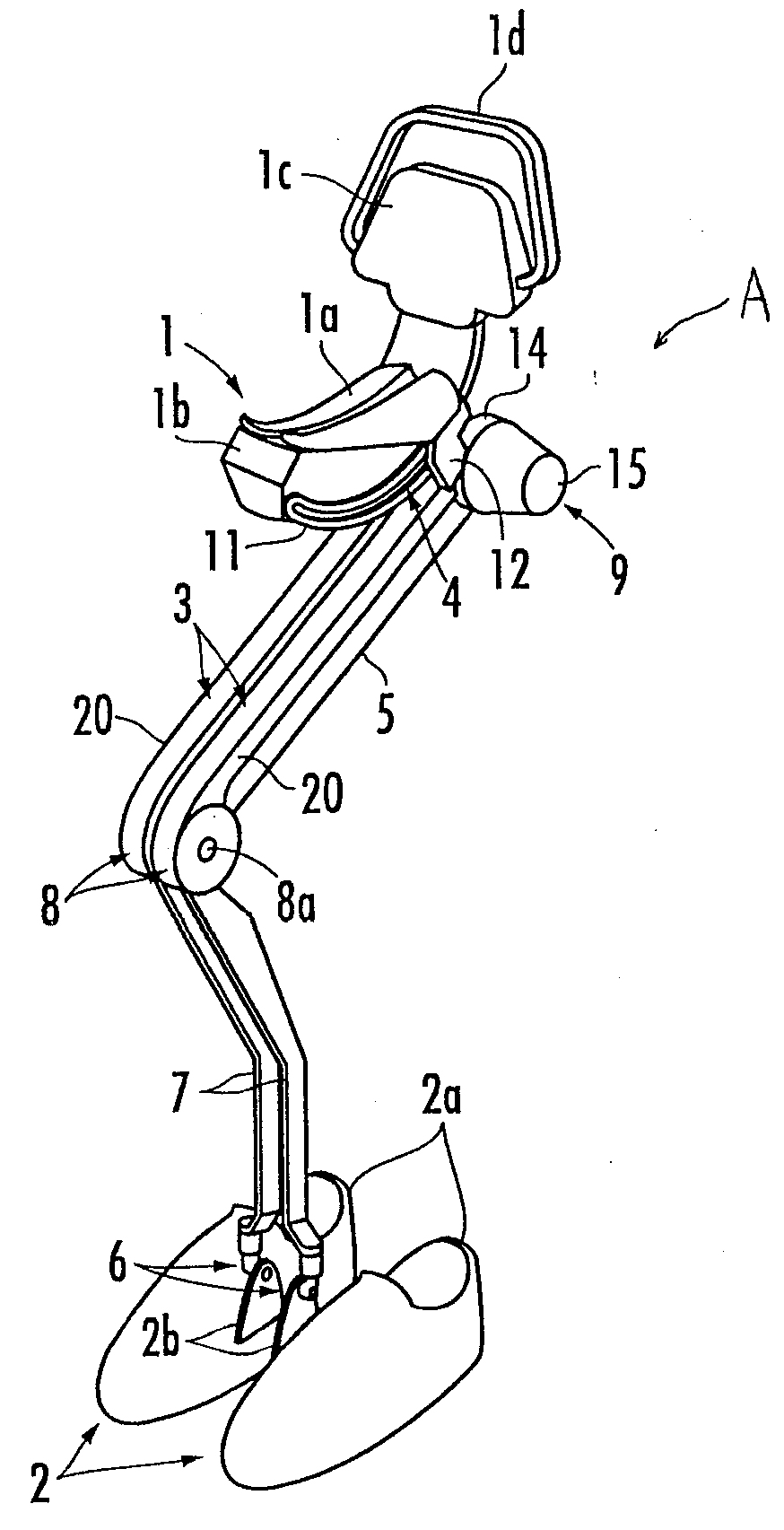
[0039]As shown, the walking assist device A of this embodiment includes a seat member 1 as a lifting force transmitting portion, a pair of left and right foot attachment portions 2 and 2 fitted to the feet of the legs of a user P, and a pair of left and right leg links 3 and 3 connecting the foot attachment portions 2 and 2 to the seat member 1. The left and right foot attachment portions 2 and 2 have the same structure and are symmetrical with each other. The left and right leg links 3 and 3 have the same structure and are symmetrical with each other, too.

[0040]The leg link 3 includes a thigh frame 5 extending downward from the seat member 1 via a first joint 4, a crus frame 7 extending upward from the foot attachment portion 2 via a second joint 6, and a third joint 8 which ...


PUM


Abstract

A power transmission system, which transmits a driving force from a rotary actuator to a third joint of a leg link, applies a driving torque to the third joint from an output shaft of the rotary actuator via a driving crank arm, a connecting rod, and a driven crank arm. A translational force (rod transmitting force) generated at the connecting rod in the longitudinal direction thereof is measured on the basis of an output of a force sensor fixed to the connecting rod. With the rod transmitting force or a driving torque applied to the third joint by the rod transmitting force as a controlled variable, the driving force of the rotary actuator is feedback-controlled according to the measured value of the rod transmitting force and a desired value of the controlled variable so that the controlled variable coincides with the desired value.

Description

BACKGROUND OF THE INVENTION[0001]1. Field of the Invention[0002]The present invention relates to a walking assist device for assisting a user (person) in walking.[0003]2. Related Background Art[0004]Conventionally, the applicant of the present application proposed this type of walking assist device, for example, in Japanese Patent Application Laid-Open No. 2007-54616 (hereinafter, referred to as Patent Document 1) or Japanese Patent Application Laid-Open No. 2007-330299 (hereinafter, referred to as Patent Document 2).[0005]These Patent Documents 1 and 2 disclose a walking assist device including a seat member on which a user is seated in a straddling manner, a pair of left and right foot attachment portions fitted to the left and right feet of the user, respectively, and a pair of left and right leg links interconnecting the seat member and the left and right foot attachment portions, respectively.[0006]In this walking assist device, each leg link includes a thigh frame extending fr...

Claims


Application Information

Patent Timeline
Patent Type & Authority Applications(United States)
IPC IPC(8): A63B71/00
CPCA61H3/008A61H2201/5061A61H2201/5069B25J9/0006A61H3/00A61H2201/1215A61H2201/5071A61H2201/1623A61H2201/1633A61H2201/1635A61H2201/1642A61H2201/165A61H2201/1676A61H2201/1436
Inventor IKEUCHI, YASUSHININOMIYA, EIJI
Owner HONDA MOTOR CO LTD
Learn More