Centrifuge and centrifuging method

a centrifugal and centrifugal technology, applied in centrifugal force sediment separation, centrifuges, separation processes, etc., can solve the problems of low purity of separated materials, difficult separation of layers, so as to facilitate the separation and separation of layers

Inactive Publication Date: 2009-12-17
YANG HYUN JIN
View PDF8 Cites 16 Cited by
  • Summary
  • Abstract
  • Description
  • Claims
  • Application Information

AI Technical Summary

Benefits of technology

[0014]The present invention provides a centrifuge and a centrifuging method capable of adjusting the amount of gravitational force and centrifugal force applied to a material to be separated centrifugally, and precisely and easily dividing and separating layers of centrifugally separated material.

Problems solved by technology

The separation of centrifugally separated liquid layers requires not only an extensive amount of work, but the purity of the separated materials is low, and the separated material can be damaged.
However, this method cannot be used under general circumstances.
Additionally, it is difficult to distinguish between centrifuged layers accumulated on the wall in one dimension.
For example, when a small quantity of around 0.01 ml of a cell sample must be separated, the above method is not appropriate.
However, this type of centrifuge is not suitable for use in the biotech experiments.
When cells are separated in a centrifuge, the separated layers are visually discernible, but it is difficult to physically separate them.
If no centrifugal force is applied, because the cohesiveness and adhesiveness between cells are not very different from the characteristics of water, separating the upper layer of water has a 50% failure rate.
If more centrifugal force is used to press the cells tightly together, the cells can be damaged.

Method used


Image

  • Centrifuge and centrifuging method
  • Centrifuge and centrifuging method
  • Centrifuge and centrifuging method

Examples


Embodiment Construction

[0045]The present invention will now be described more fully with reference to the accompanying drawings, in which exemplary embodiments of the invention are shown.

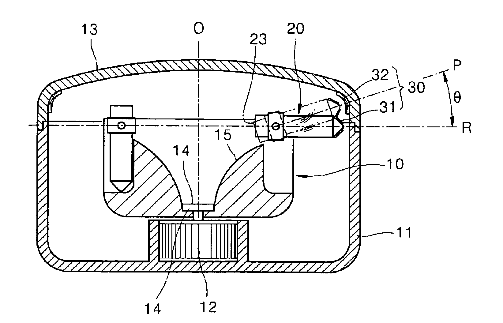
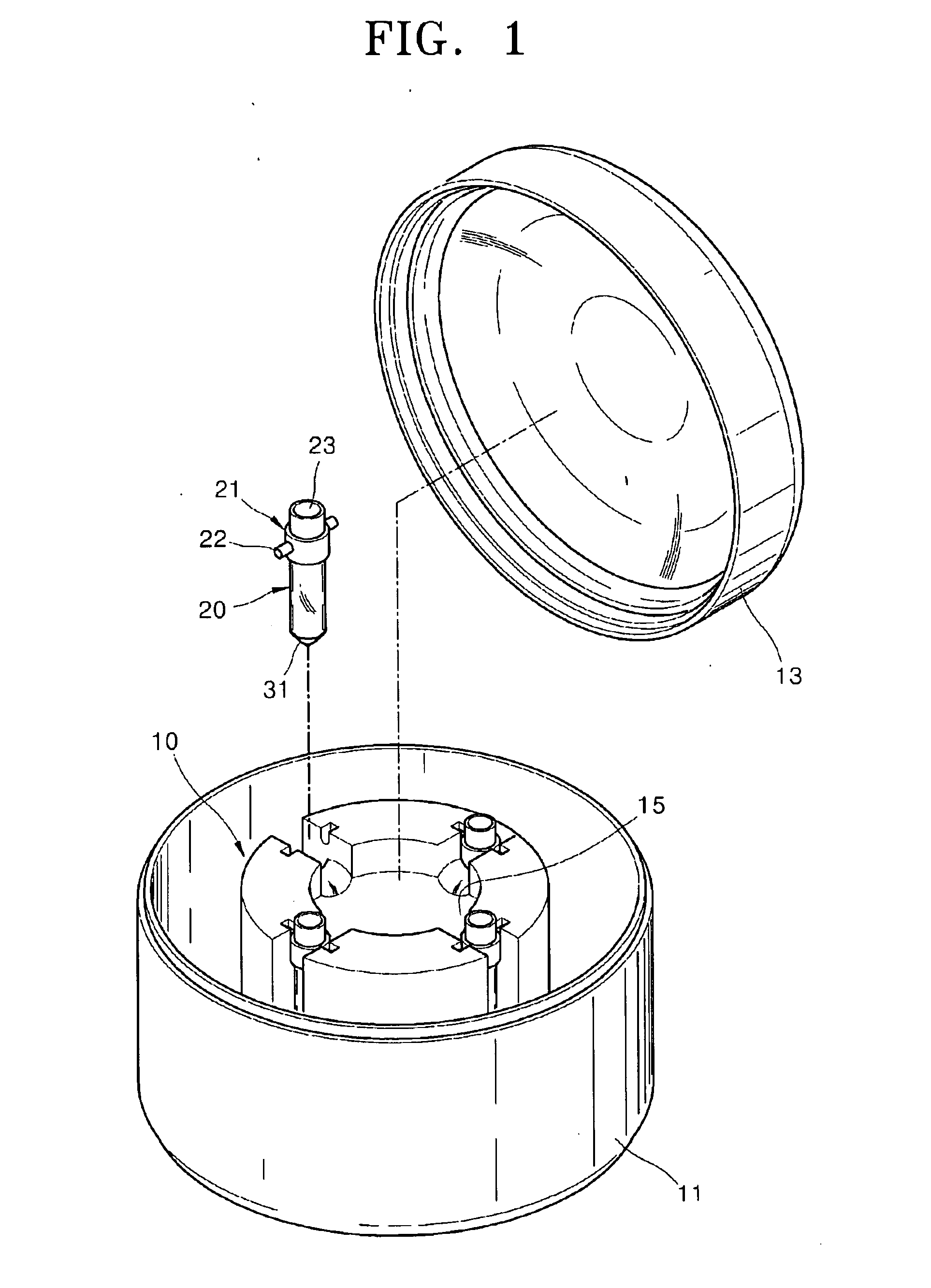
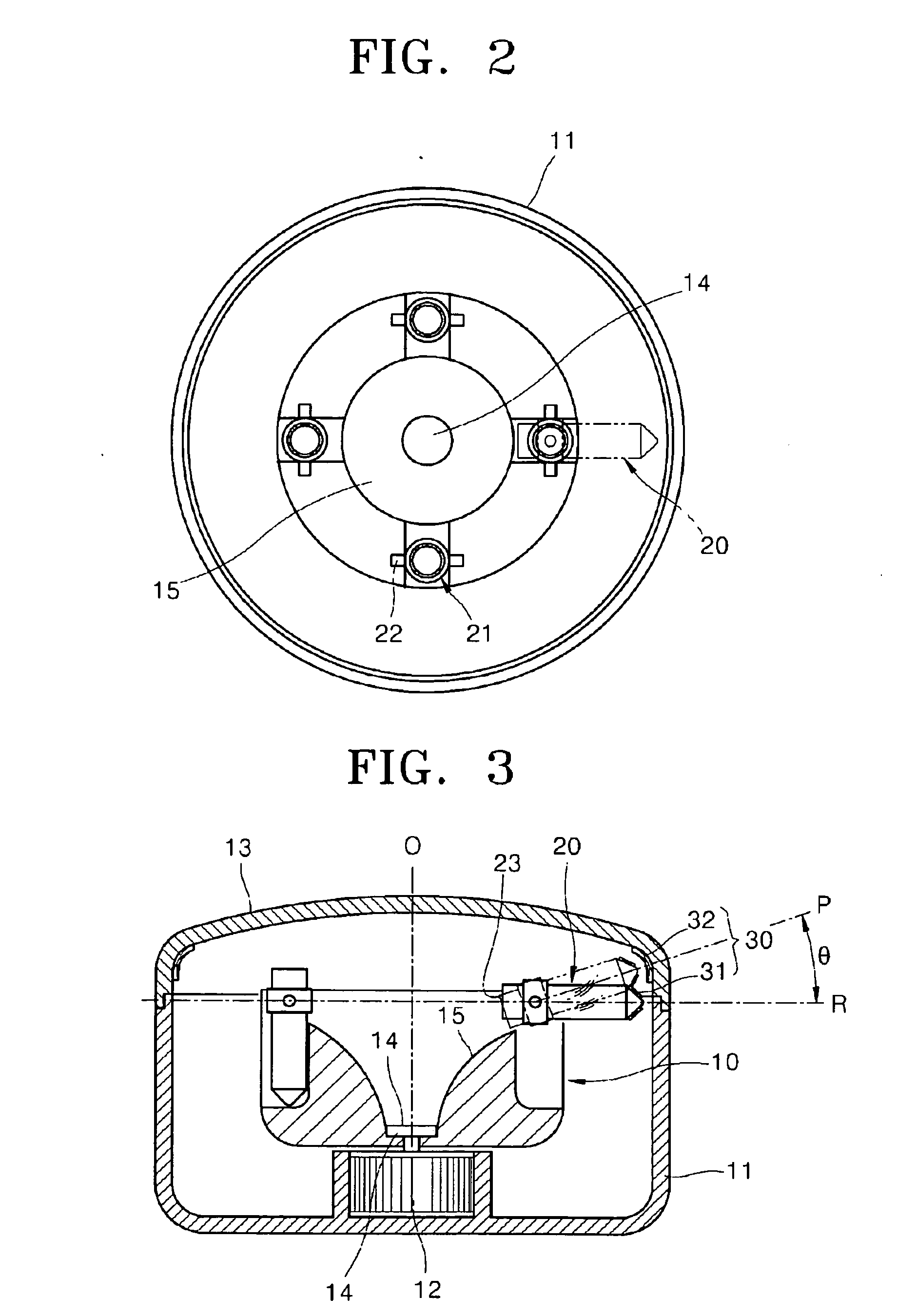
[0046]FIG. 1 is a perspective view of a centrifuge according to an embodiment of the present invention, FIG. 2 is a plan view of the centrifuge in FIG. 1, and FIG. 3 is a cross-sectional side view of the centrifuge in FIG. 1.

[0047]A centrifuge according to the embodiment illustrated in FIGS. 1 through 3 is an apparatus that spins about a rotation axis 14 to separate materials. The centrifuge of the present embodiment includes a rotor 10, a container 20 pivotably coupled to the rotor 10, and an angle adjuster 30 that adjusts the rotation angle of the container 20.

[0048]The rotor 10 rotates about the rotation axis 14, and supports the container 20. The rotor 10 is disposed within a casing 11, and is coupled to a drive motor 12 to rotate within the casing 11 and perform centrifugal separation. The centrifuge also includes a ...


PUM

PropertyMeasurementUnit
angleaaaaaaaaaa
angleaaaaaaaaaa
pivoting angleaaaaaaaaaa

Abstract

Provided are a centrifuge that rotates about a rotation axis to separate a material and a method of centrifugal separation. The container is coupled to the centrifuge to freely pivot upward and downward on a pivoting axis vertical to a rotation plane. The container has an opening at an upper end thereof and holds a material inside. An angle adjuster raises the central axis of the container beyond a perpendicular angle with the rotation axis while the centrifuge is rotating in order to arrange the opening of the container downward with respect to the rotation plane and point an end of the container opposite to the opening of the container upward with respect to the rotation plane, and allow a portion of layers formed during centrifugal separating to flow down through the opening.

Description

CROSS-REFERENCE TO RELATED PATENT APPLICATION[0001]This application is a national phase of International Application No. PCT / KR2007 / 002127, entitled “CENTRIFUGE AND CENTRIFUGING METHOD”, which was filed on Apr. 30, 2007, and which claims priority of Korean Patent Application No. 10-2006-0051461, filed on Jun. 8, 2006 and Korean Patent Application No. 10-2006-0111264, filed on Nov. 10, 2006, respectively, in the Korean Intellectual Property Office, the disclosure of which is incorporated herein in its entirety by reference.BACKGROUND OF THE INVENTION[0002]1. Field of the Invention[0003]The present invention relates to a centrifuge and a centrifuging method, and more particularly, to a centrifuge and a centrifuging method capable of performing centrifugal separating while simultaneously placing the opening of a container to face downward by rotating the container about a pivoting axis by more that 90° so that accurate and easy recovery of material can be performed.[0004]According to t...

Claims


Application Information

Patent Timeline
Patent Type & Authority Applications(United States)
IPC IPC(8): B04B9/10
CPCB04B9/10B04B5/0421
Inventor YANG, HYUN-JIN
Owner YANG HYUN JIN
Why Eureka
Try Eureka