

Exhaust emission control device
a technology of exhaust emission control and control device, which is applied in the direction of machines/engines, mechanical equipment, separation processes, etc., can solve problems such as affecting the mountability of vehicles, and achieve the effect of high pressure and higher flow ra
- Summary
- Abstract
- Description
- Claims
- Application Information
AI Technical Summary
Benefits of technology
Problems solved by technology
Method used
Image

Examples
Embodiment Construction
[0049]Embodiments of the invention will be described in conjunction with the drawings.
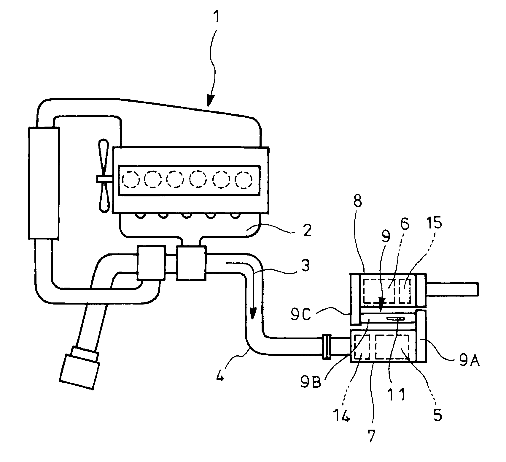
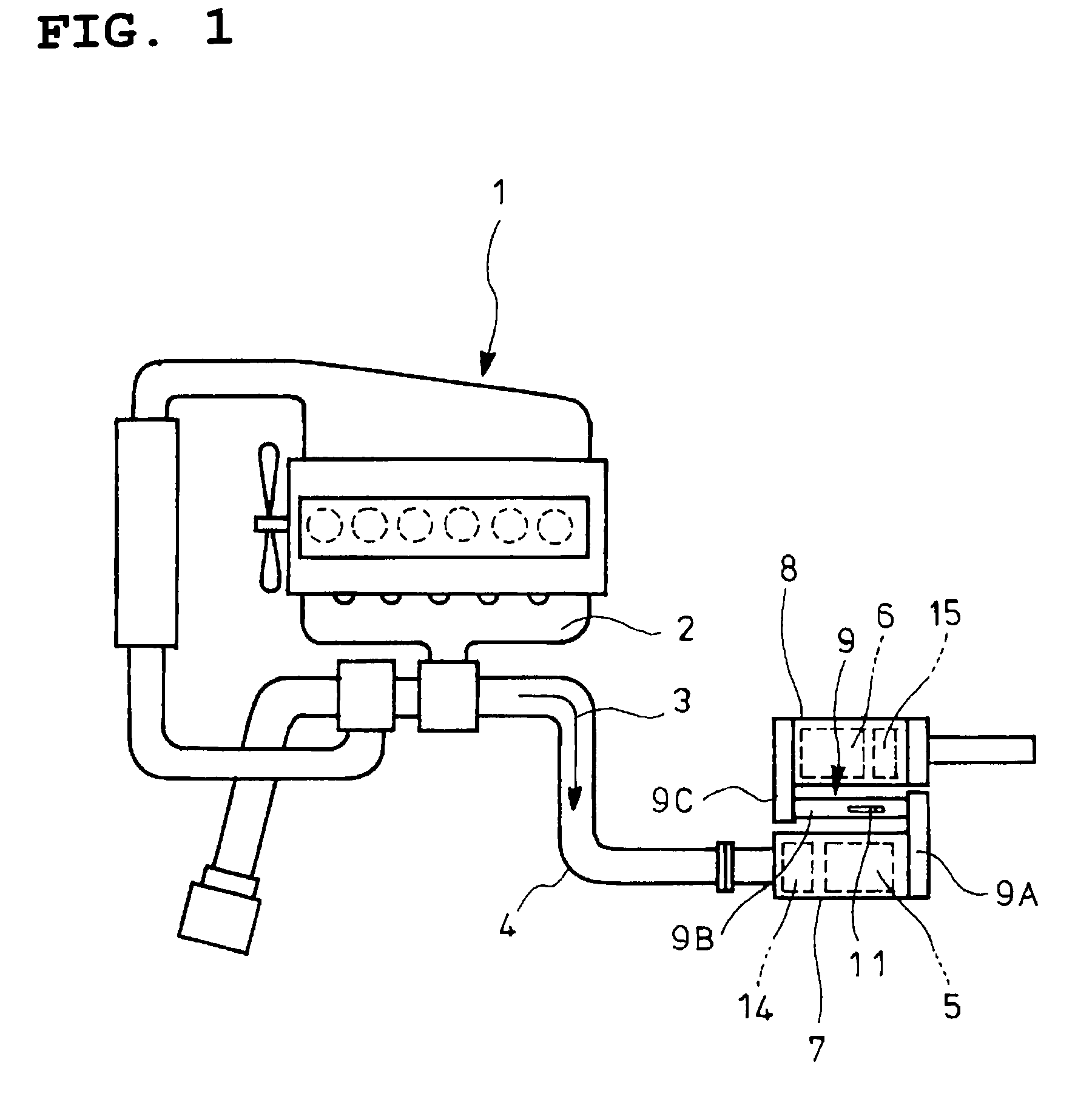
[0050]FIGS. 4 and 5 show an embodiment of the invention which is directed to an exhaust emission control device constructed substantially similar to that shown in FIGS. 1 and 2 mentioned in the above, a gas gathering chamber 9A and a mixing pipe 9B constituting an upstream portion of the communication passage 9 being changed as mentioned below.
[0051]Specifically, in the embodiment illustrated, slits 12 (openings) are formed in circumferentially spaced positions on a rear end of a mixing pipe 9B so as to introduce exhaust gas 3, a downstream end 9a of a gas gathering chamber 9A being connected to the rear end of the mixing pipe 9B such that the respective slits 12 are encased and the rear end of the mixing pipe 9B is closed.
[0052]The respective slits 12 on the rear end of the mixing pipe 9B are adjusted to have openings with areas gradually increased from upstream side to downstream side of the exha...
PUM
| Property | Measurement | Unit |
|---|---|---|
| swirling force | aaaaa | aaaaa |
| areas | aaaaa | aaaaa |
| dispersion | aaaaa | aaaaa |
Abstract
Description
Claims
Application Information