
Treatment of fly ash

a technology of fly ash and treatment method, which is applied in the direction of solid waste management, sustainable waste treatment, and solid waste management, can solve the problems of high processing cost and fly ash is a commodity, and achieve the effects of accelerating reaction speed, effective surface oxidation, and enhancing the ionized air

Inactive Publication Date: 2009-12-24
MATRIX INC
View PDF21 Cites 32 Cited by
  • Summary
  • Abstract
  • Description
  • Claims
  • Application Information

AI Technical Summary

Benefits of technology

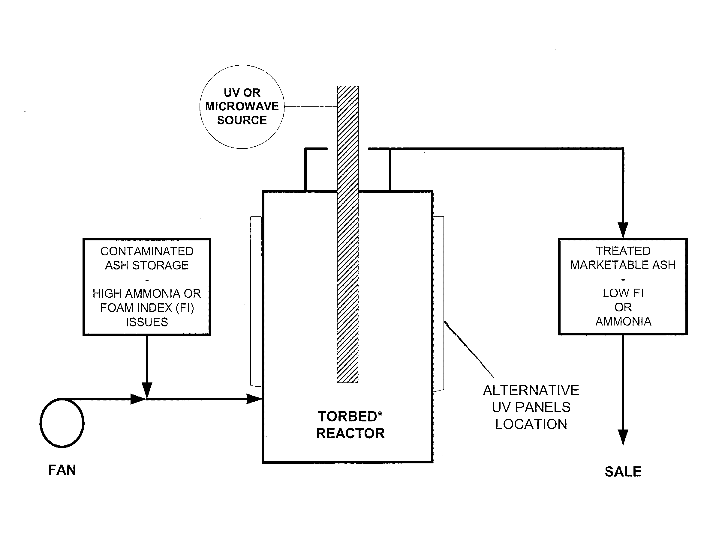
[0027]The present application seeks to beneficiate a variety of different coal burning power plant fly ash materials that either have a high foam index problem or are contaminated with ammonia or a combination of these issues and are not marketable into the cement / concrete industry. It also seeks to overcome the shortcomings of the aforementioned methods and provide a safe, economical method of treatment of ash.
[0028]In the methodology of the present application, a surface blocking mechanism is employed that minimizes the energy requirements for processing the ash. It does not require heating. The treatment only modifies superficial layers of the fly ash while the gaseous agent itself has a half-life that is measured in seconds or at most minutes. Fly ash is a commodity and cannot stand high costs in processing to bring it into a marketable state. Accordingly, what is proposed in this application is specifically a low cost method of upgrading the ash merely by localized surface treatment of the offending carbon. The unique aspect of the application is the careful administration of ionized air generated from ambient humid air for ionic treatment of the surface of the carbon utilizing a contacting method and environment operating at, or close to, ambient temperature. (Air is specifically mentioned due to its low cost, although oxygen or oxygen-enriched air may be used, provided there is sufficient humidity in it). Thus, the operational cost of heating material and the associated capital cost of thermal equipment is avoided.Dosage g / kg of fly ashIonized Air0.0040.390.771.55MethodInputOutputInputOutputInputOutputInputOutputFoam Index95709530100259515Reduction26.3%68.4%75.0%84.2%Dosage g / kg of fly ashOzone0.310.611.22MethodInputOutputInputOutputInputOutput3.06Foam Index958510580105909580Reduction10.5%23.8%14.3%15.7%

Problems solved by technology

Fly ash is a commodity and cannot stand high costs in processing to bring it into a marketable state.

Method used


Image

  • Treatment of fly ash
  • Treatment of fly ash
  • Treatment of fly ash

Examples


Embodiment Construction

[0080]While the invention will be described and disclosed here in connection with certain preferred embodiments, the description is not intended to limit the invention to the specific embodiments shown and described here, but rather the invention is intended to cover all alternative embodiments and modifications that fall within the spirit and scope of the invention as defined by the claims included herein as well as any equivalents of the disclosed and claimed invention.

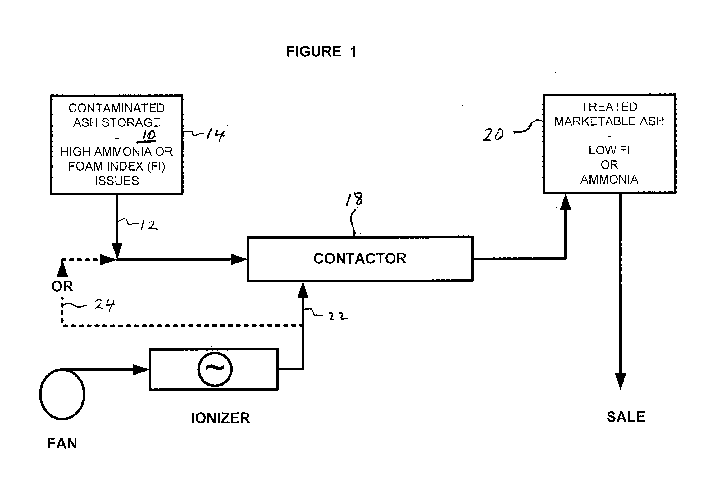
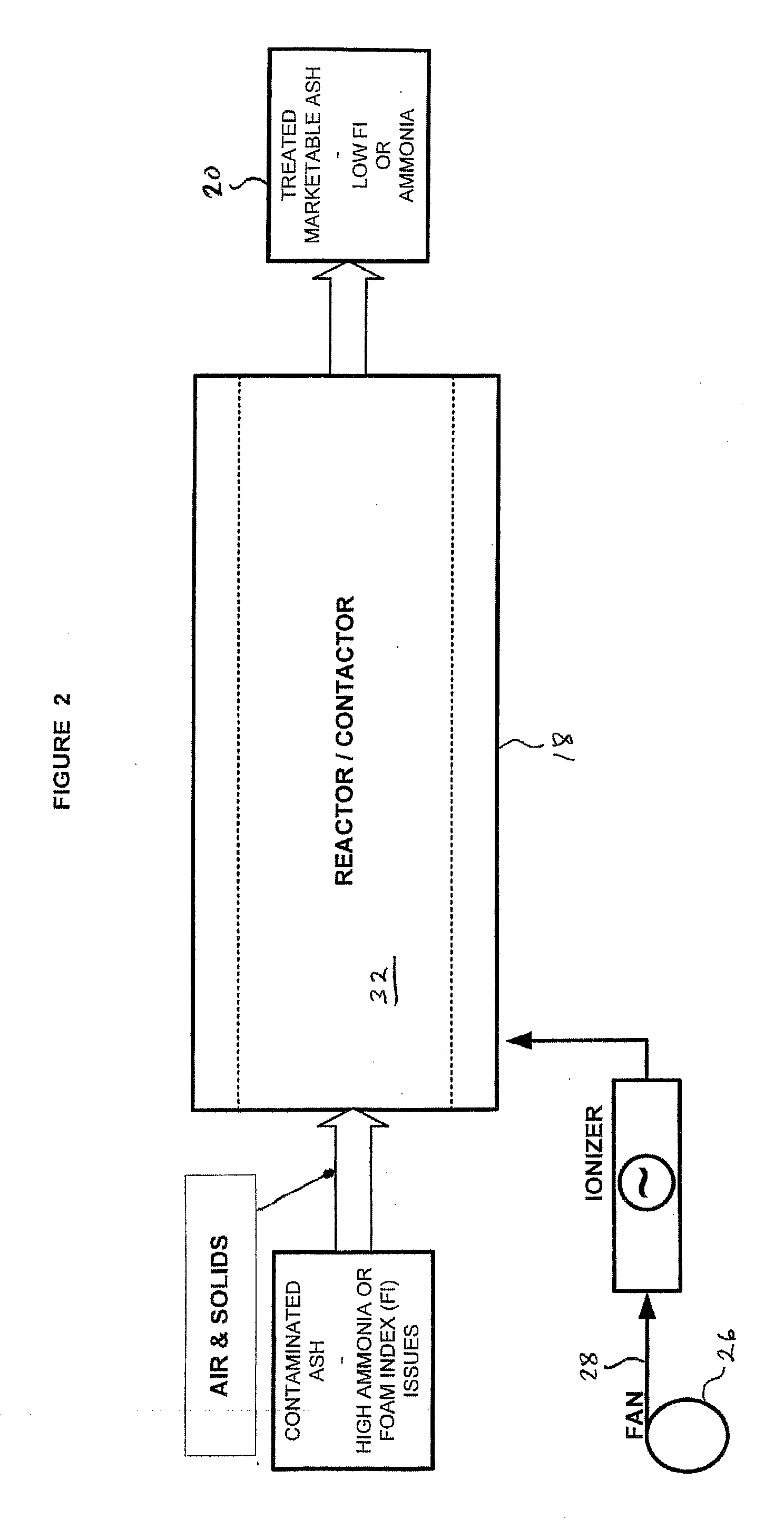
[0081]Turning now to the accompanying drawings, it will be understood that FIG. 1 indicates the conveyance of particulate fly ash 10 in a gas stream 12 from a feed hopper or silo 14, which contains the fly ash containing carbon to be treated, through a contactor or reactor 18 to a product hopper or silo 20. Generally, an ionized gas 22 can be an additive to the air stream that is conveying the fly ash. In certain cases, it may be appropriate to make all the ionized gas present in the conveying stream itself rather t...


PUM

PropertyMeasurementUnit
Temperatureaaaaaaaaaa
Fractionaaaaaaaaaa

Abstract

Treated carbon-containing fly ash with reduced surfactant-adsorbing capacity is prepared by processing involving contacting the fly ash with ionized gas prepared from a humid gas feed, such as humid air. Treated fly ash with reduced ammonia content is prepared by processing involving contacting the fly ash with ionized gas prepared from a humid gas feed, such as humid air, or exposing the fly ash to microwave radiation or ultraviolet radiation.

Description

CROSS-REFERENCE TO RELATED APPLICATIONS[0001]This application is a continuation-in-part of U.S. patent application Ser. No. 11 / 974,905 entitled “Plasma Treatment Of Fly Ash From Coal Combustion To Improve Its Marketability” filed Oct. 16, 2007, which claims priority to U.S. provisional patent application 60 / 852,318 entitled “Treatment Of Fly Ash From Coal Combustion To Improve Its Marketability” filed Oct. 17, 2006.[0002]This application is a continuation-in-part of U.S. patent application Ser. No. 11 / 974,934 entitled “Treatment Of Fly Ash From Coal Combustion To Improve Its Marketability” filed Oct. 16, 2007, which claims priority to U.S. provisional patent application 60 / 852,318 entitled “Treatment Of Fly Ash From Coal Combustion To Improve Its Marketability” filed Oct. 17, 2006.[0003]This application is a continuation-in-part of International Patent Application No. PCT / US2007 / 022209 entitled “Treatment Of Fly Ash From Coal Combustion To Improve Its Marketability” filed Oct. 17, 2...

Claims


Application Information

Patent Timeline
IPC IPC(8): C04B18/06C25B1/00B01J19/12
CPCC04B18/08C04B20/023Y02W30/91
Inventor WHELLOCK, JOHN G.
Owner MATRIX INC
Learn More