Shielded Wire-Grounding construction

Inactive Publication Date: 2009-12-24
AUTONETWORKS TECH LTD +2
View PDF3 Cites 26 Cited by
  • Summary
  • Abstract
  • Description
  • Claims
  • Application Information

AI Technical Summary

Benefits of technology

[0084]As described above, in the present invention, the drain wires of the shielded wire and the ground wire are connected to each other by the crimping connection by using the intermediate crimping terminal or by twisting the drain wires and the ground wire or through the joint bus bar. Therefore as compared with the case in which the drain wires and the ground wire are connected to each other by welding the portion of the drain wire to be connected and the portion of the ground wire to be connected to each other, it is possible to decrease the lead-out length of the drain wire to 40 mm at the shortest. Because it is possible to decrease the peeling length of the shielded wire by the above-described length, it is possible to enhance the shielding performance of shielded wire.
[0085]Further the peeling length of the sheath of the shielded wire and the length of the exposed portion of each drain wire are short. Therefore in connecting a plurality of the drain wires to the ground wire, it is unnecessary to perform a tape-winding operation to align the front ends of the drain wires with each other. Thus it is po

Problems solved by technology

Thus the resistance welding cannot be performed in a production line.
Another problem is that because the peeling length of the sheath is long, it is necessary to band the drain wires together with the tape 3

Method used


Image

  • Shielded Wire-Grounding construction
  • Shielded Wire-Grounding construction
  • Shielded Wire-Grounding construction

Examples


Example

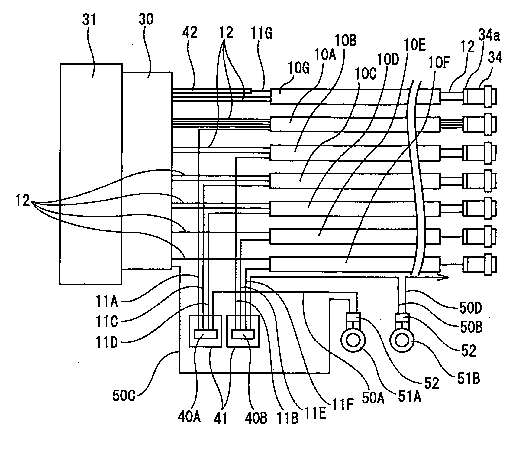
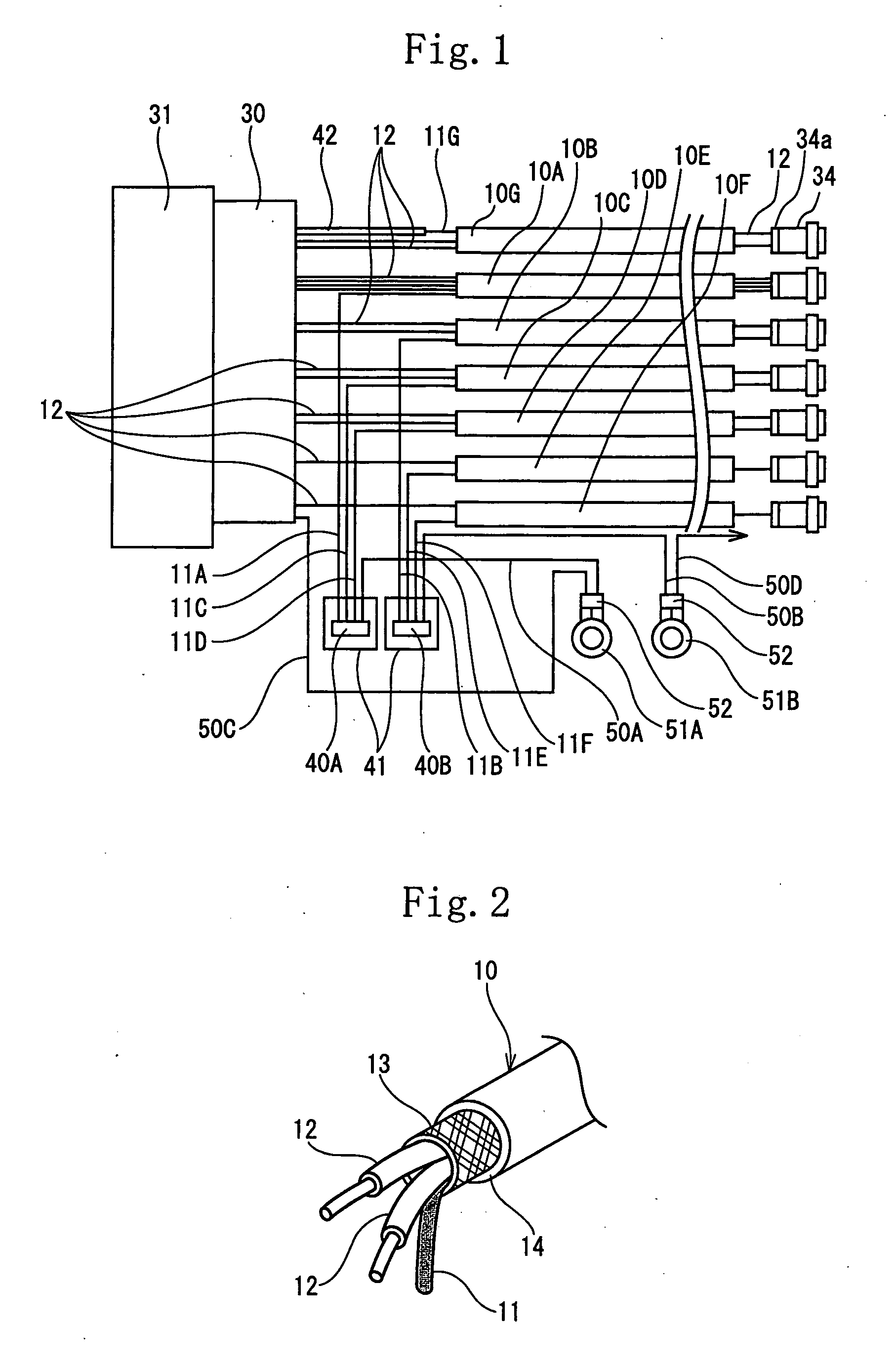
[0132]FIGS. 1 through 6 show a first embodiment of the present invention.

[0133]As shown in FIG. 4, a wire harness W / H composed of a plurality of shielded wires 10 and an electric wire 20 other than the shielded wire 10 is wired in an engine room of a car. An end of the wire harness W / H is connected to one connector 30 connected to a fuel injection control apparatus 31 by fitting the connector 30 in the fuel injection control apparatus 31.

[0134]As shown in FIG. 2, the shielded wire 10 is composed of one or a plurality of core wires 12 consisting of insulated coated electric wires which constitute one or a plurality of signal wires and one drain wire 11. The drain wire 11 and the core wires 12 are coated with a shielding layer 13 consisting of a metal foil or a tube of a braided metal and a sheath 14 made of an insulating resin material, with the shielding layer 13 coated with the sheath 14. The drain wire 11 is brought into contact with the shielding layer 13 to make the shielding la...

Example

[0174]FIGS. 11 and 12 show a second embodiment.

[0175]In the second embodiment, the method of connecting the drain wire 11 and the ground wire 50 with each other is different from that of the first embodiment. The drain wire 11 and the ground wire 50 are connected with each other by twisting strands of the drain wire 11 and those of the ground wire 50.

[0176]More specifically, as shown in FIG. 12, the strands of the drain wire 11 and those of the ground wire 50 are untwisted, bundled, and twisted to form a connected portion 43. After the connected portion 43 is covered with a cylindrical heat-shrinkable tube 44, the heat-shrinkable tube 44 is heated to shrink it so that the heat-shrinkable tube 44 adheres to a peripheral surface of the connected portion 43.

[0177]The heat-shrinkable tube 44 is a waterproof shrinkable tube containing a thermoplastic adhesive agent in its inner wall. By thermally shrinking the heat-shrinkable tube 44, the adhesive agent fuses, thus adhering to the outer ...

Example

[0183]FIGS. 14 and 15 show a third embodiment.

[0184]In the third embodiment, the construction of the ground wire to be connected with the drain wire 11 is different from that of the above-described embodiments.

[0185]More specifically, as shown in FIG. 15, a ground wire 53 consists of a single core wire having a conductor covered with an insulating coating 54. A connector accommodation terminal 56 accommodated inside the connector 30 is connected to a conductor 55a exposed at one end of the ground wire 53 by peeling the insulating coating 54, whereas a conductor 55b disposed at the other end of the ground wire 53 is connected to the drain wires 11A, 11C, and 11D by means of the intermediate crimping terminal 40A. The sectional area of the conductor 55 of the ground wire 53 is set to 0.5 mm2, 0.75 mm2 or 1.25 mm2. The core electric wire 12 is connected to the connector 30 connected with the connector accommodation terminal 56 connected with the ground wire 53.

[0186]As shown in FIG. 15...


PUM


Abstract

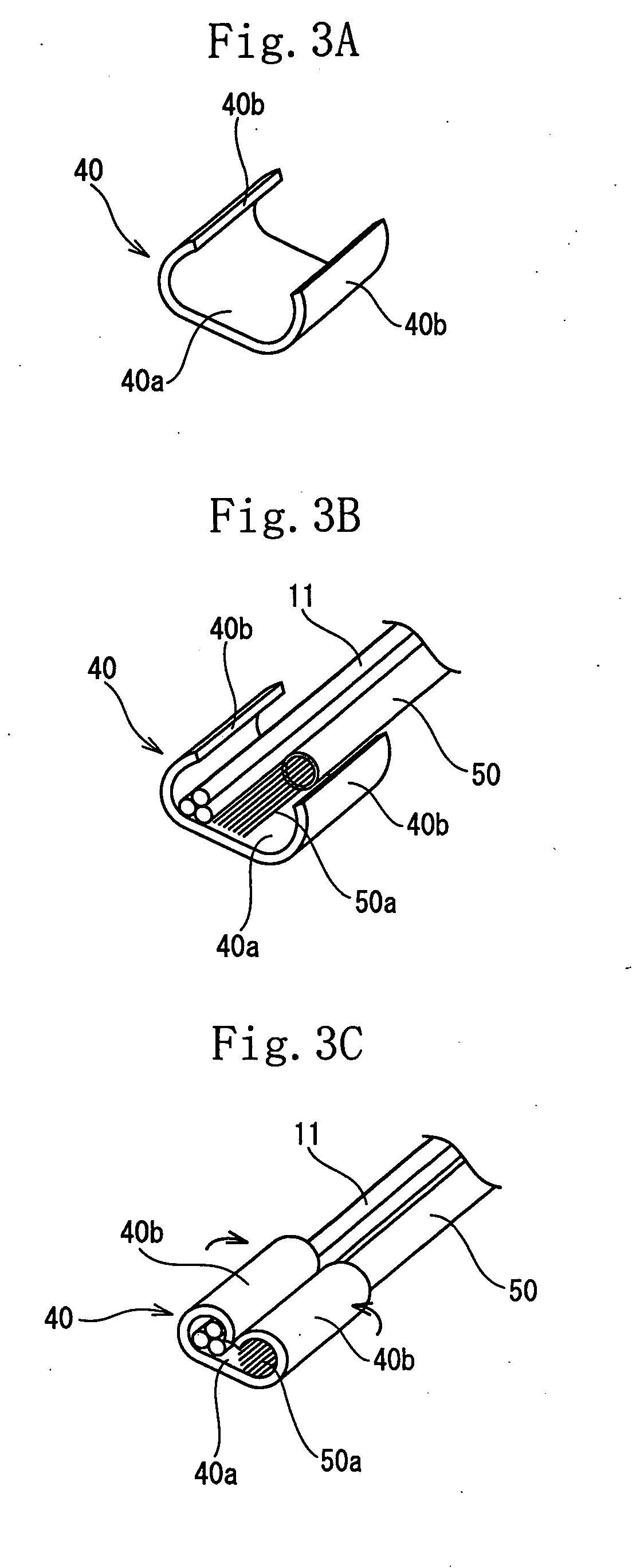
The lead-out side end of a drain wire (11) led out from a shield wire (10) and either a conductor exposed to one end of a ground wire (50), to the other end of which a ground terminal (51) is connected, or a conductor exposed to one end of a ground wire (53), to the other end of which a connector receiving terminal (56) is connected, are collectively connected together by crimping by using a U-shape cross-sectioned intermediate crimp terminal (40) formed by a pair of opposed barrels (40b), or connected by twisting them together, or connected through a joint bus bar.

Description

TECHNICAL FIELD[0001]The present invention relates to a shielded wire-grounding construction and a shielded wire-grounding method. More particularly the present invention is intended to provide a slim construction for connecting a drain wire lead out from an end of the shielded wire and a ground wire to each other.BACKGROUND ART[0002]Conventionally it is necessary to insert a core electric wire consisting of one or a plurality of insulated coated electric wires into a braided tube made of metal-fibers or into a metal foil for shielding use and connect the shielded wire composed of the braided metal tube or the metal foil covered with a sheath (insulating coating) to a ground wire.[0003]In Japanese Patent Application Laid-Open No. 2000-268893 (patent document 1), as shown in FIG. 19, after ends of the sheath for a plurality of the shielded wires 1A through 1F is peeled to expose the braided metal, the braided metal is twisted to obtain the drain wires 1a through 1f. The drain wires 1...

Claims


Application Information

Patent Timeline
IPC IPC(8): H02G15/02
CPCH01R4/184H01R4/726H01R9/034H01R9/0512H01R2201/26H01R13/52H01R24/562H01R2105/00H01R9/0518H01R13/65914
Inventor HAGI, MASAHIROYAMANO, YOSHIAKINISHIMURA, NAOYASAIJO, KATSUTOSHIBABA, HIROTAKAICHIKAWA, MASAHARUYAMADA, AKIRA
Owner AUTONETWORKS TECH LTD
Why Eureka
Try Eureka