Damper device and manufacture of such a damper device

a technology of damper device and damper, which is applied in the direction of vibration dampers, mechanical instruments, resilient suspensions, etc., can solve the problems of increased risk of cavitation, heavy demands on shock absorbers, and vehicles used in extreme ambient conditions, so as to simplify machining and reduce product manufacturing costs

Inactive Publication Date: 2009-12-24
OHLINS
View PDF11 Cites 34 Cited by
  • Summary
  • Abstract
  • Description
  • Claims
  • Application Information

AI Technical Summary

Benefits of technology

[0009]Since the three parts (i.e., the damper body, the pressurization reservoir and the valve housing) are generally parallel to one another, connecting ports can be arranged between the internal spaces of the different parts. Placing valve devices at either end of the valve housing and connecting the space between the valve devices to the pressurized space in the pressurization reservoir creates a damper that functions with a positive pressure in both the compression chamber and the return chamber. Because a positive pressure build-up prevails, the likelihood of cavitation can be reduced while the damping force characteristic in both stroke directions can be adjusted separately and independently of each another with the external adjustments.
[0010]In some configurations, the valve devices are located concentrically apart at either end of the valve housing part. This location of the valve devices facilitates the transport of damping medium between the two damping chambers and allows an easy external adjustment of the valve devices. In addition, to simplify manufacture, valve devices of identical design can be used for compression damping and for return damping.
[0011]Locating the valve devices close to the compression and return chambers makes it possible to create large port areas, which means that the flow resistance of the damping medium to and from the valves is minimized.
[0013]Positioning the cone and the spring inside the valve seat simplifies machining and affords lower product manufacturing costs because the valve seat is relatively sunken and no machining of the valve is required inside the valve seat space.

Problems solved by technology

Vehicles used under extreme ambient conditions, such as over difficult terrain, in heat and in dust, place heavy demands on shock absorbers.
High damping forces result in large pressure drops over the piston, which increase the risk of cavitation.
The damper described above lacks the ability to pressurize the damping medium on both sides of the piston, which means that cavitation can easily occur when the damping medium flows through the flow-restricting third and fourth bore cavities.
The problem with this construction is that the damper is not externally adjustable but has a fixed damping characteristic that can only be modified by dismantling the damper and changing the flow-damping shims in the piston.
Pressurization of the damper also occurs on only one side of the piston, which can lead to cavitation problems.

Method used


Image

  • Damper device and manufacture of such a damper device
  • Damper device and manufacture of such a damper device
  • Damper device and manufacture of such a damper device

Examples


Embodiment Construction

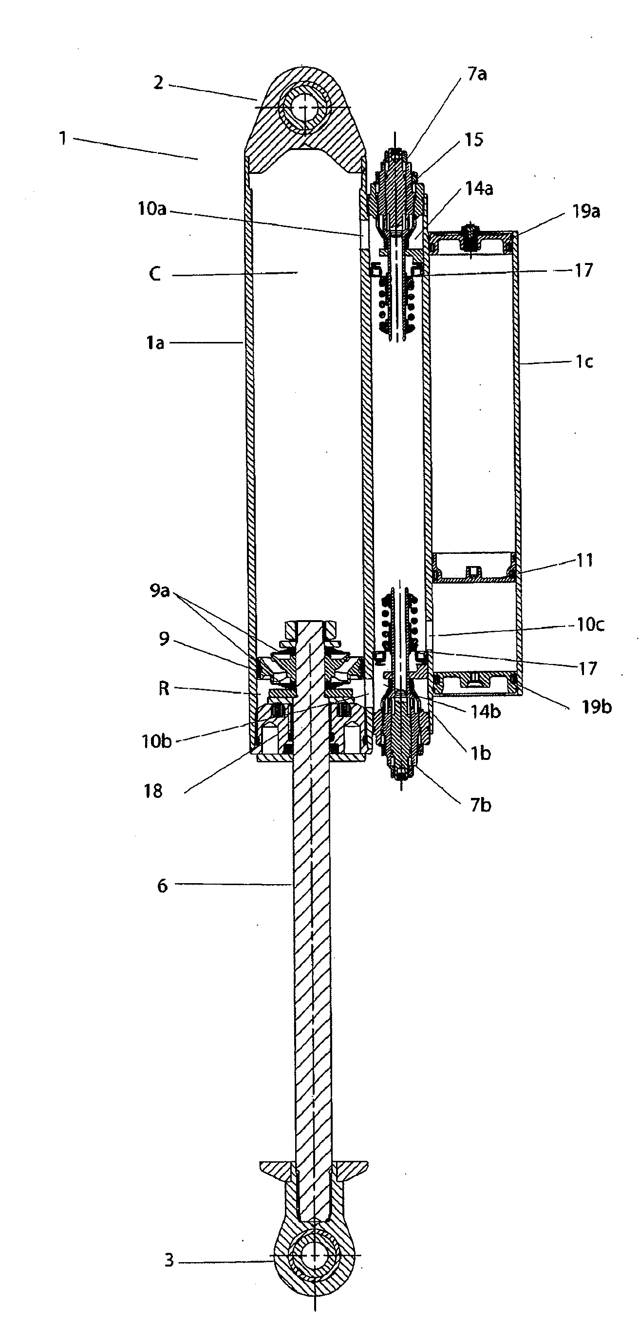
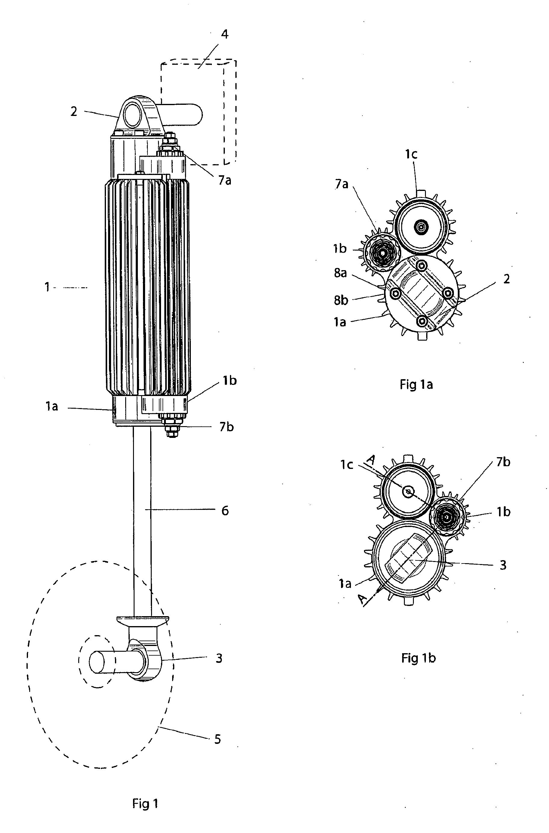
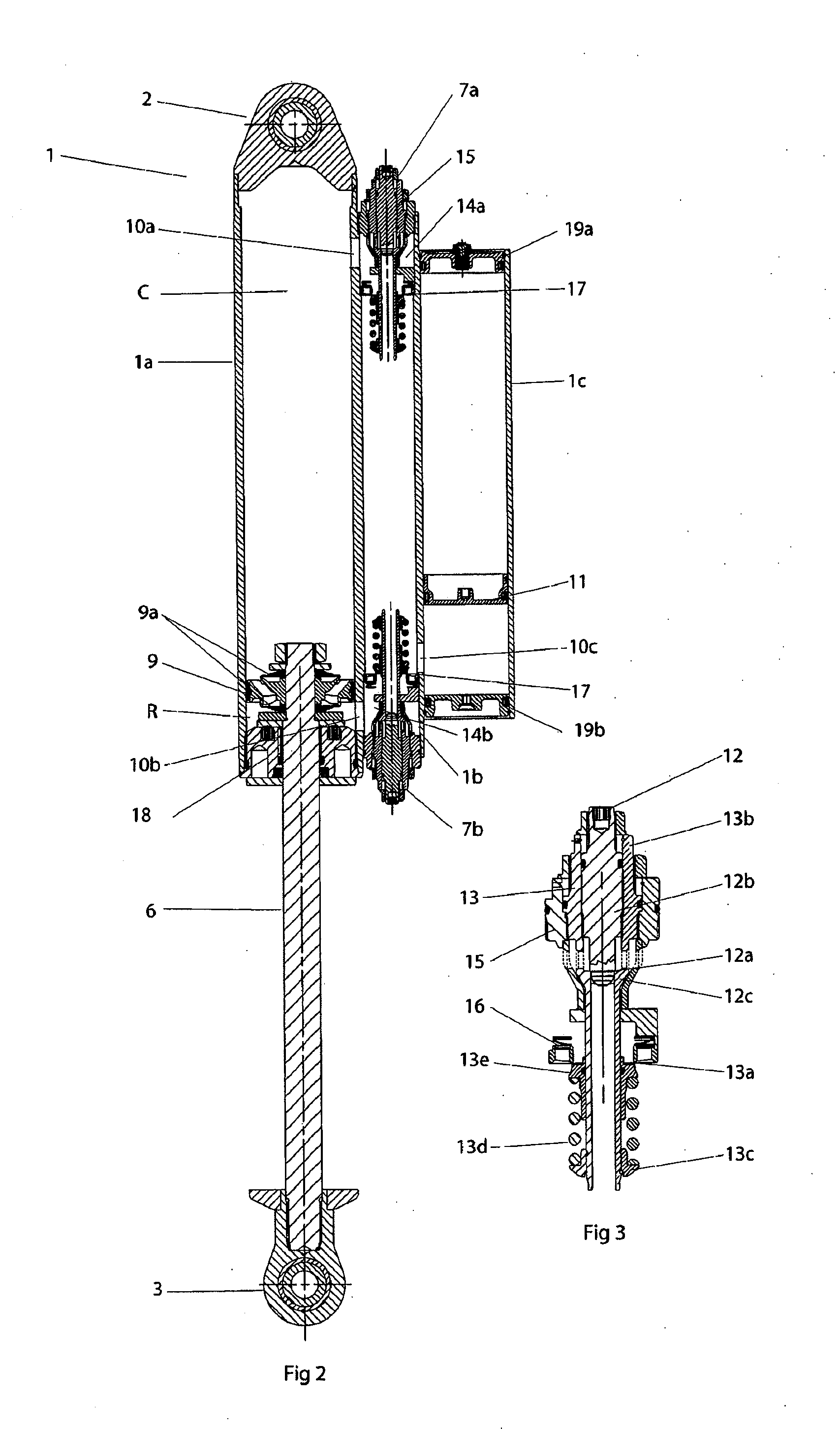
[0020]FIG. 1 shows a damper device comprising a body 1, an upper eye 2 of which is fixed to a portion of a vehicle chassis 4 and a lower eye 3 of which is fixed to a wheel mounting 5. Mounting of the damper device is shown only schematically in the drawing. In some configurations, more than one damper can be used for each wheel in conjunction with most suitable types of known wheel suspension arrangements provided that there is sufficient space. The illustrated damper device preferably is used together with a spring element, such as a leaf spring or a coil spring. For example, the coil spring can be placed around another supplementary shock absorber.

[0021]The lower eye 3 is fitted to a piston rod 6, which moves in and out of the damper body 1a during relative movements between the chassis 4 and the wheel 5. Also visible in FIG. 1 are valve devices 7a, 7b, which are mounted in line, apart from one another at either end of a valve housing 1b.

[0022]FIG. 1a shows a top plan view of the...


PUM


Abstract

A damper device is manufactured from a single integrated body. The damper device comprises a damping chamber portion, a valve housing portion with adjustable valve devices and a pressurization reservoir portion. The internal volume of the damping chamber portion is divided by a piston into a compression chamber and a return chamber and the internal volume of the pressurization reservoir portion is divided by a member that is acted upon by a pressure that pressurizes the damping medium in the device. The three different portions are arranged substantially parallel to one another and the internal volume of the valve housing is connected both to the pressurized interior of the pressurization reservoir and to both chambers of the damping chamber part so that the damper always functions with a positive pressure in both the compression and the return chamber. The body is extruded as a single workpiece with alternating heat-conducting channels and fins on its outer surface.

Description

CROSS-REFERENCE TO RELATED APPLICATIONS[0001]This application claims the benefit and priority to and is a U.S. National Phase of PCT International Application No. PCT / SE2007 / 000262, filed on Mar. 16, 2007, designating the United States of America and published on Sep. 27, 2007 as WO 2007 / 108747 in the English language, which claims priority under 35 USC 119 to Swedish Application No. 0600629-0, filed on Mar. 20, 2006. The disclosures of the above-referenced applications are hereby expressly incorporated by reference in their entireties.BACKGROUND OF THE INVENTION[0002]1. Field of the Invention[0003]The present invention generally relates to a damper device in the form of a shock absorber in which a piston acts in a damping medium in order to damp movement between wheels and chassis of a vehicle. More particularly, the present invention relates to a damper device in which three chambers are formed in parallel with the middle chamber connecting the outer chambers and one of the outer ...

Claims


Application Information

Patent Timeline
Patent Type & Authority Applications(United States)
IPC IPC(8): F16F9/34
CPCF16F9/06F16F9/44F16F9/42F16F9/3235B60G15/062B62K25/06F16F9/084
Inventor NYGREN, NILS-GORAN
Owner OHLINS
Why Eureka
Try Eureka