Vehicular air-conditioning system and control method of same

Inactive Publication Date: 2009-12-24
TOYOTA JIDOSHA KK
View PDF20 Cites 40 Cited by
  • Summary
  • Abstract
  • Description
  • Claims
  • Application Information

AI Technical Summary

Benefits of technology

[0016]This invention provides a vehicular air-conditioning system which prevents an unpleasant sensation from being imparted to an occupant due to the temperatur

Problems solved by technology

With an air-conditioner, if the temperature of the engine coolant is low as is the case when the engine is warming up, for example, the desired heating ability is unable to be obtained.
If the heating ability is insufficient, low temperature (i.e., cool) air is blown out which may by unpleasant for occupants.
Also, if the vehicle cabin starts to be heated using engine coolant while the engine is warming up, the engine coolant may end up being cooled by the heater core, thus lengthening the time that it takes for the engine to warm up.
Meanwhile, in a vehicle that is running, the volume of supply air that is blown into the vehicle cabin changes according to the pressure (i.e., ram pressure) against the front of the vehicle, which may

Method used


Image

  • Vehicular air-conditioning system and control method of same
  • Vehicular air-conditioning system and control method of same
  • Vehicular air-conditioning system and control method of same

Examples


Embodiment Construction

[0051]In the following description and the accompanying drawings, the present invention will be described in more detail in terms of example embodiments.

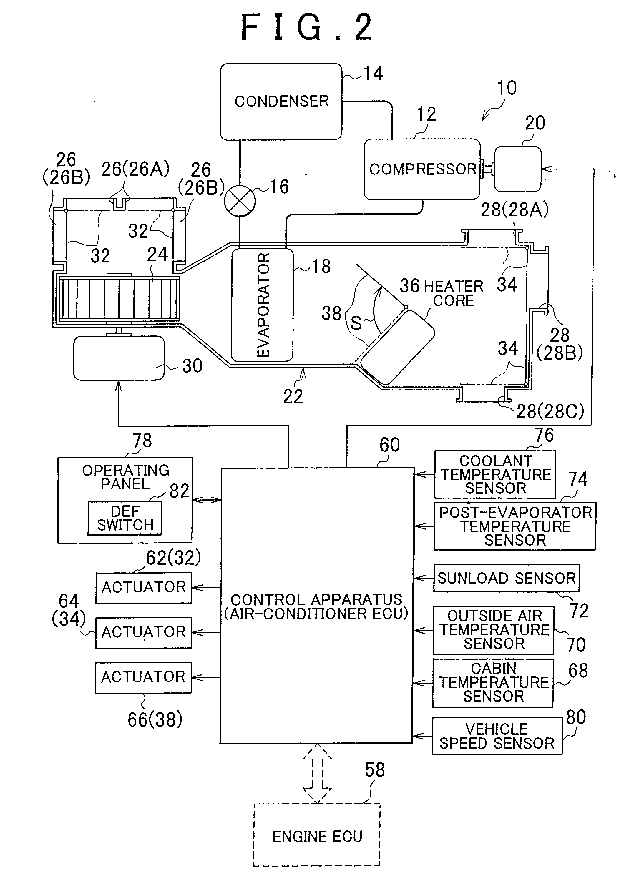
[0052]FIG. 2 is a block diagram schematically showing a vehicular air-conditioning system (hereinafter simply referred to as “air-conditioner”) 10 in an example embodiment.

[0053]In this air-conditioner 10, a refrigeration cycle is created in which refrigerant is circulated by a compressor 12, a condenser 14, an expansion valve 16, and an evaporator 18.

[0054]The compressor 12 is driven by a compressor motor 20 so as to compress refrigerant. This high temperature, high pressure refrigerant is then sent to the condenser 14. In the condenser 14, the high temperature, high pressure refrigerant is cooled so that is liquefies. This liquefied refrigerant is then sent to the evaporator 18.

[0055]In the evaporator 18, the liquefied refrigerant is vaporized. At this time, air passing through the evaporator 18 is cooled. The expansion valve 16 r...


PUM


Abstract

An air-conditioner ECU sets the maximum flowrate or a set flowrate which is less than the maximum flowrate as a required flowrate Vr based on outside air temperature when a DEF mode is selected, and requires that coolant be circulated (steps 100 to 110). Also, when the coolant temperature Tw during heating is between a set temperature TS3 and a set temperature TS1, circulation of coolant at the minimum flowrate is required (steps 134, 130, 132). When a blower fan is stopped when the coolant temperature is equal to or less than the set temperature TS3 and a fresh air mode is selected, the circulation of coolant at the minimum flowrate is required when the vehicle speed Sv is above a set vehicle speed (steps 134 to 146). Cool air is prevented from being blown out of an air outlet and heating of the coolant is promoted by suppressing the speed of an electric pump while maintaining the ability to prevent fogging.

Description

BACKGROUND OF THE INVENTION[0001]1. Field of the Invention[0002]The invention relates to a vehicular air-conditioning system which produces a flow of supply air the temperature of which has been adjusted using coolant of an internal combustion engine, and a control method of that vehicular air-conditioning system.[0003]2. Description of the Related Art[0004]In an air-conditioning system (hereinafter simply referred to as “air-conditioner”) provided in a vehicle having an internal combustion engine (hereinafter simply referred to as “engine”) as a driving source for running, supply air is heated using engine coolant that is circulated between a heater core provided as a heat exchanger for heating, and the engine. This engine coolant is circulated between the engine, an engine radiator, and the heater core by a water pump which is driven by the driving force of the engine.[0005]Vehicles in which engine stop control is performed, which stops the engine when a preset engine stop conditi...

Claims


Application Information

Patent Timeline
IPC IPC(8): B60H1/04B60H1/00
CPCB60H1/00764B60H1/00885B60H1/00828B60H1/00778
Inventor NEMOTO, ATSUKIINUI, KIWAMUMORITA, MASAKI
Owner TOYOTA JIDOSHA KK
Why Eureka
Try Eureka