Eureka AIR delivers breakthrough ideas for toughest innovation challenges, trusted by R&D personnel around the world.

Sawtooth wave generating circuit and switch mode power supply device having the same

Inactive Publication Date: 2009-12-24
SAMSUNG ELECTRONICS CO LTD
View PDF5 Cites 7 Cited by
  • Summary
  • Abstract
  • Description
  • Claims
  • Application Information

AI Technical Summary

Benefits of technology

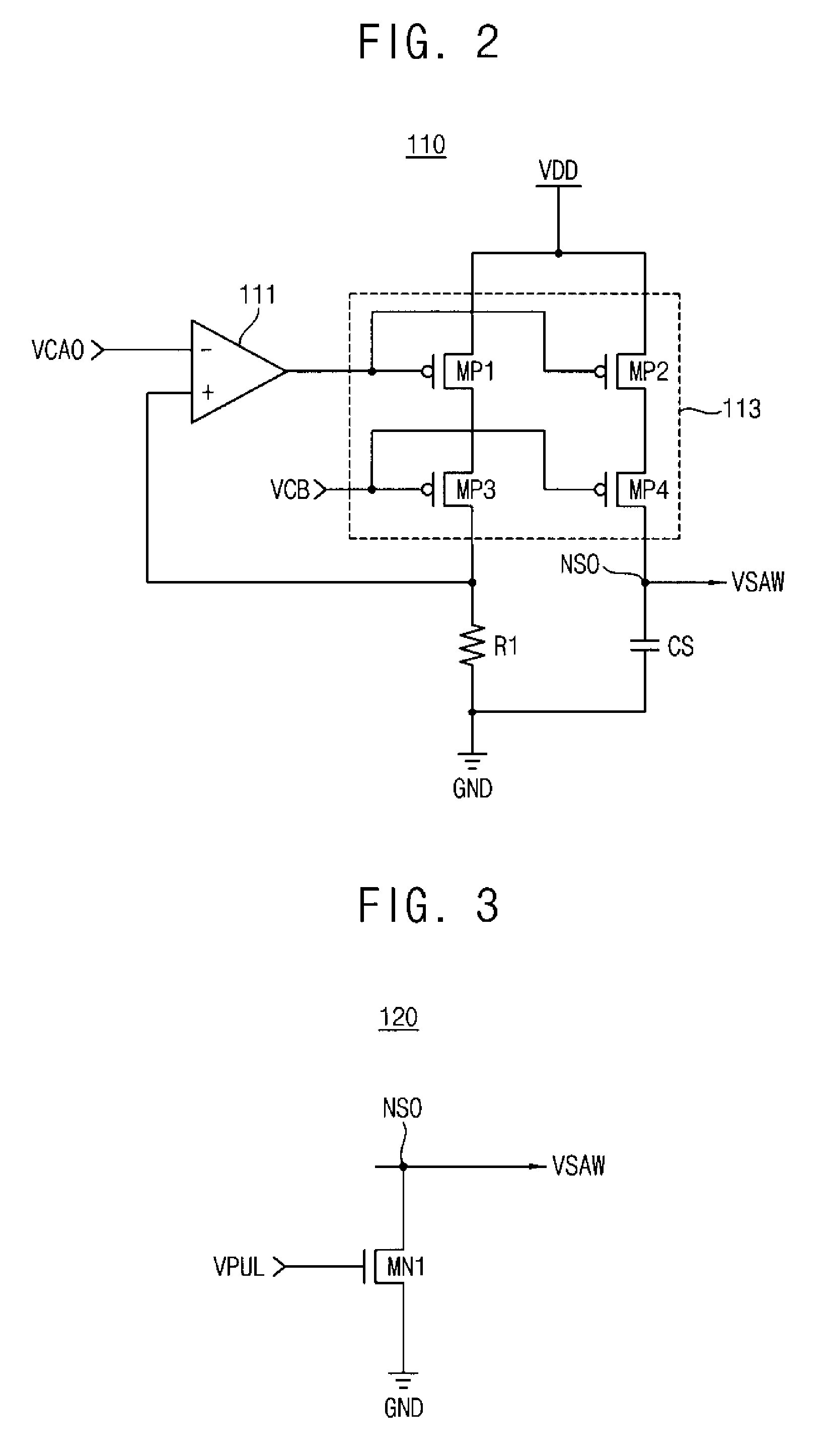
[0022]The charging circuit may include an amplifier, a current supplying circuit and a resistor. The amplifier may amplify the calibration output signal, a current supplying circuit may supply a charging current in response to an output signal of the amplifier, and a resistor may maintain the charging current.
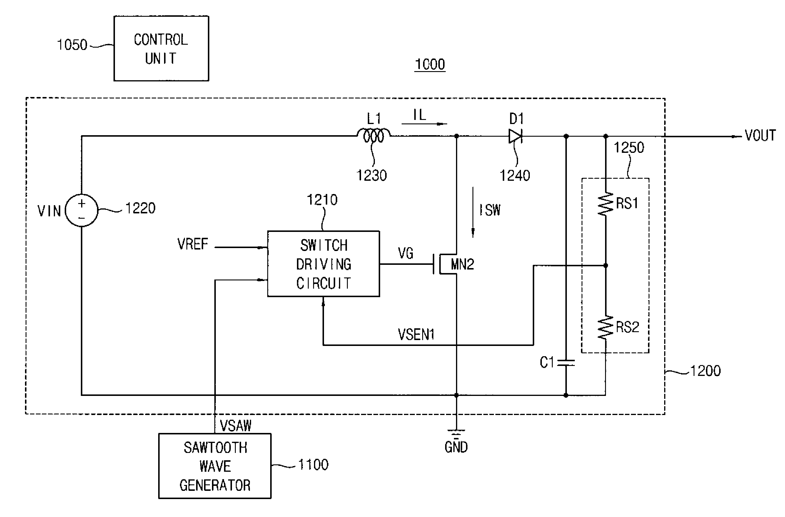
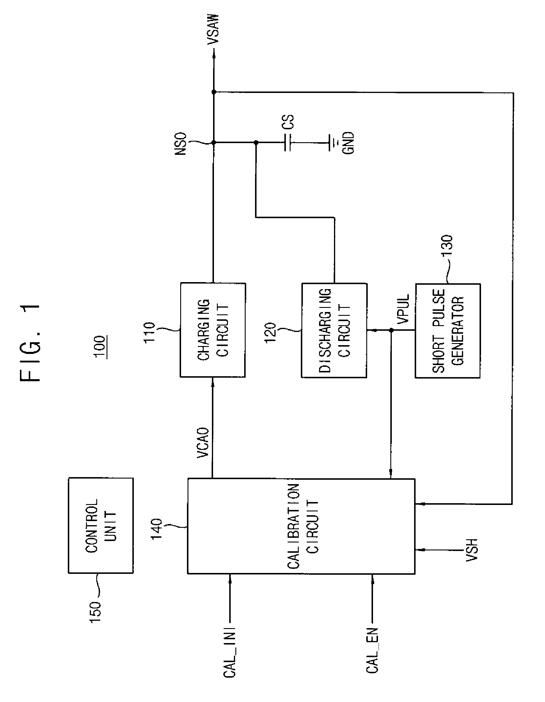
[0037]Therefore, the sawtooth wave generating circuit according to the embodiments may determine an optimum charging current for a fabrication process, an operating voltage, or an operating temperature because the sawtooth wave generating circuit performs calibration on a sawtooth wave signal. Therefore, the sawtooth wave generating circuit according to the embodiments may generate a stable sawtooth wave signal even though a frequency, a fabrication process, an operating voltage, or an operating temperature may be changed. The DC-DC converter or the switch mode power supply device including the sawtooth wave generating circuit may generate a switch control signal that drives a power device using a calibrated sawtooth wave signal. Therefore, the switch mode power supply device including the sawtooth wave generating circuit according to the embodiments may generate a stable switch control signal and a stable DC output voltage even though a frequency, a fabrication process, an operating voltage, or an operating temperature may be changed.

Problems solved by technology

Therefore, conventionally it was difficult to generate a sawtooth wave signal having a desired slope.
If the slope of a sawtooth wave signal is fixed, a waveform of the sawtooth wave signal may be distorted when a frequency of the sawtooth wave signal is very large, and amplitude of the sawtooth wave signal may be too small when a frequency of the sawtooth wave signal is very small.

Method used


Image

  • Sawtooth wave generating circuit and switch mode power supply device having the same
  • Sawtooth wave generating circuit and switch mode power supply device having the same
  • Sawtooth wave generating circuit and switch mode power supply device having the same

Examples


Embodiment Construction

[0055]Embodiments of the present general inventive concept now will be described more fully with reference to the accompanying drawings, in which embodiments of the present general inventive concept are illustrated. This general inventive concept may, however, be embodied in many different forms and should not be construed as limited to the embodiments set forth herein. Rather, these embodiments are provided so that this disclosure will be thorough and complete, and will fully convey the scope of the present general inventive concept to those skilled in the art. Like reference numerals refer to like elements throughout this application.

[0056]It will be understood that, although the terms first, second, etc. may be used herein to describe various elements, these elements should not be limited by these terms. These terms are used to distinguish one element from another. For example, a first element could be termed a second element, and, similarly, a second element could be termed a fi...


PUM


Abstract

A sawtooth wave generating circuit that outputs a sawtooth wave signal after calibration and a switch mode power supply device including the sawtooth wave generating circuit is disclosed. The sawtooth wave generating circuit includes a capacitor, a calibration circuit, a charging circuit, discharging circuit and a control unit. The calibration circuit feedbacks a sawtooth wave signal, generates a plurality of voltage signals based on the sawtooth wave signal, and selects one of the voltage signals to generate a calibration output signal. Therefore, the sawtooth wave generating circuit generates a stable sawtooth wave signal regardless of operating conditions.

Description

CROSS-REFERENCE TO RELATED APPLICATIONS[0001]This application claims priority under 35 USC §119 from Korean Patent Application No. 2008-59124, filed on Jun. 23, 2008 in the Korean Intellectual Property Office (KIPO), the disclosure of which is incorporated herein in its entirety by reference.BACKGROUND[0002]1. Field of the General Inventive Concept[0003]The embodiments relate to a sawtooth wave generating circuit, and more particularly to a switch mode power supply device having the sawtooth wave generating circuit.[0004]2. Description of the Related Art[0005]Generally, a power supply device that supplies a power source is required to operate electronic devices. Recently a switch mode power supply (SMPS) device that supplies a stable DC output voltage is used in electronic devices.[0006]The SMPS device converts a DC input voltage into stable output voltages that have various values by controlling a current through an inductor, using semiconductor devices as switching devices. The SM...

Claims


Application Information

Patent Timeline
IPC IPC(8): G05F1/46H03K4/48
CPCH03K4/50H02M3/155H03K4/08
Inventor CHUNG, KYU-YOUNG
Owner SAMSUNG ELECTRONICS CO LTD
Why Eureka
Eureka Blog
Learn More