

Manually Pre-Settable Proof of Flow Current Sensor Apparatus, System, and/or Method
- Summary
- Abstract
- Description
- Claims
- Application Information
AI Technical Summary
Benefits of technology
Problems solved by technology
Method used
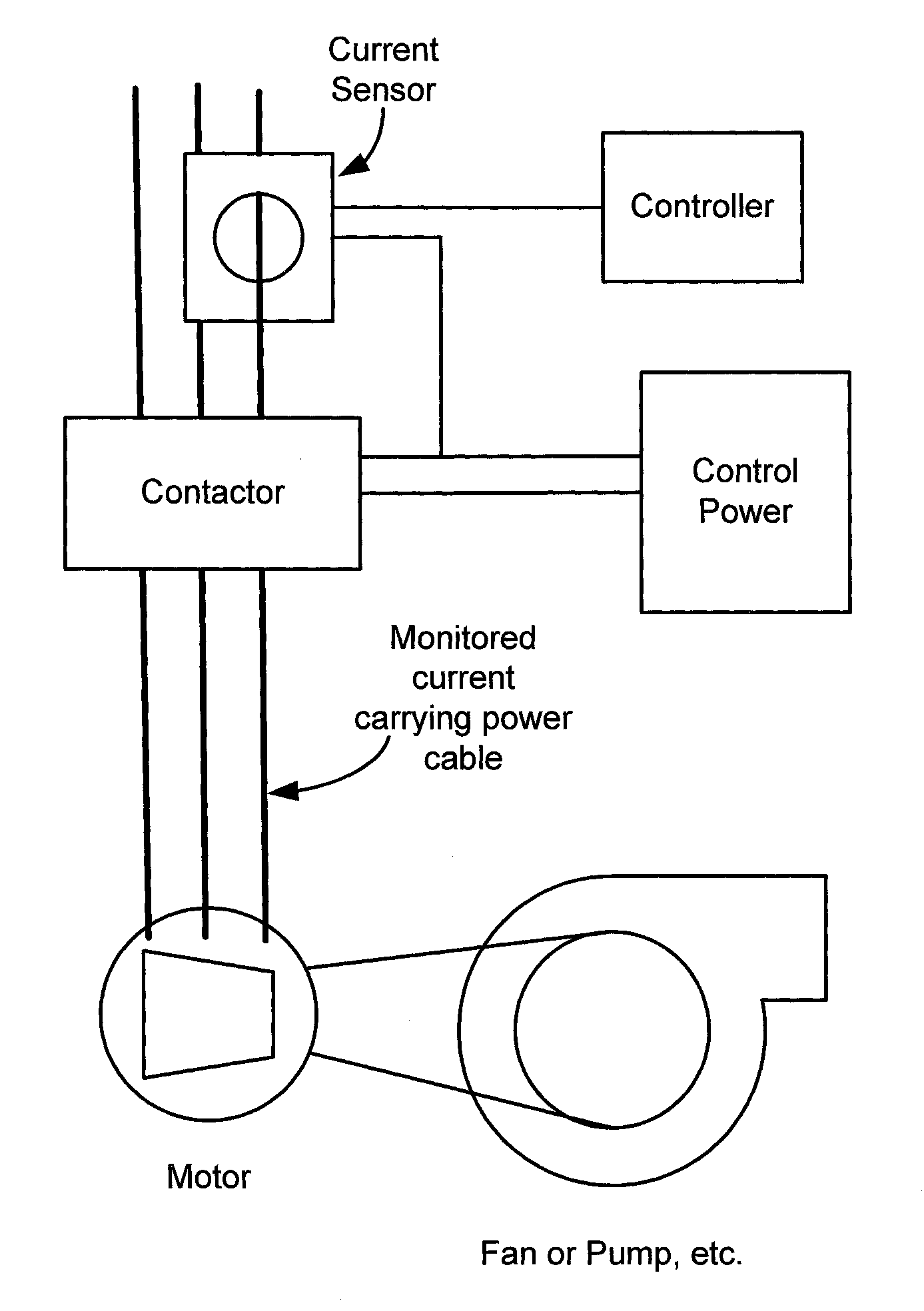
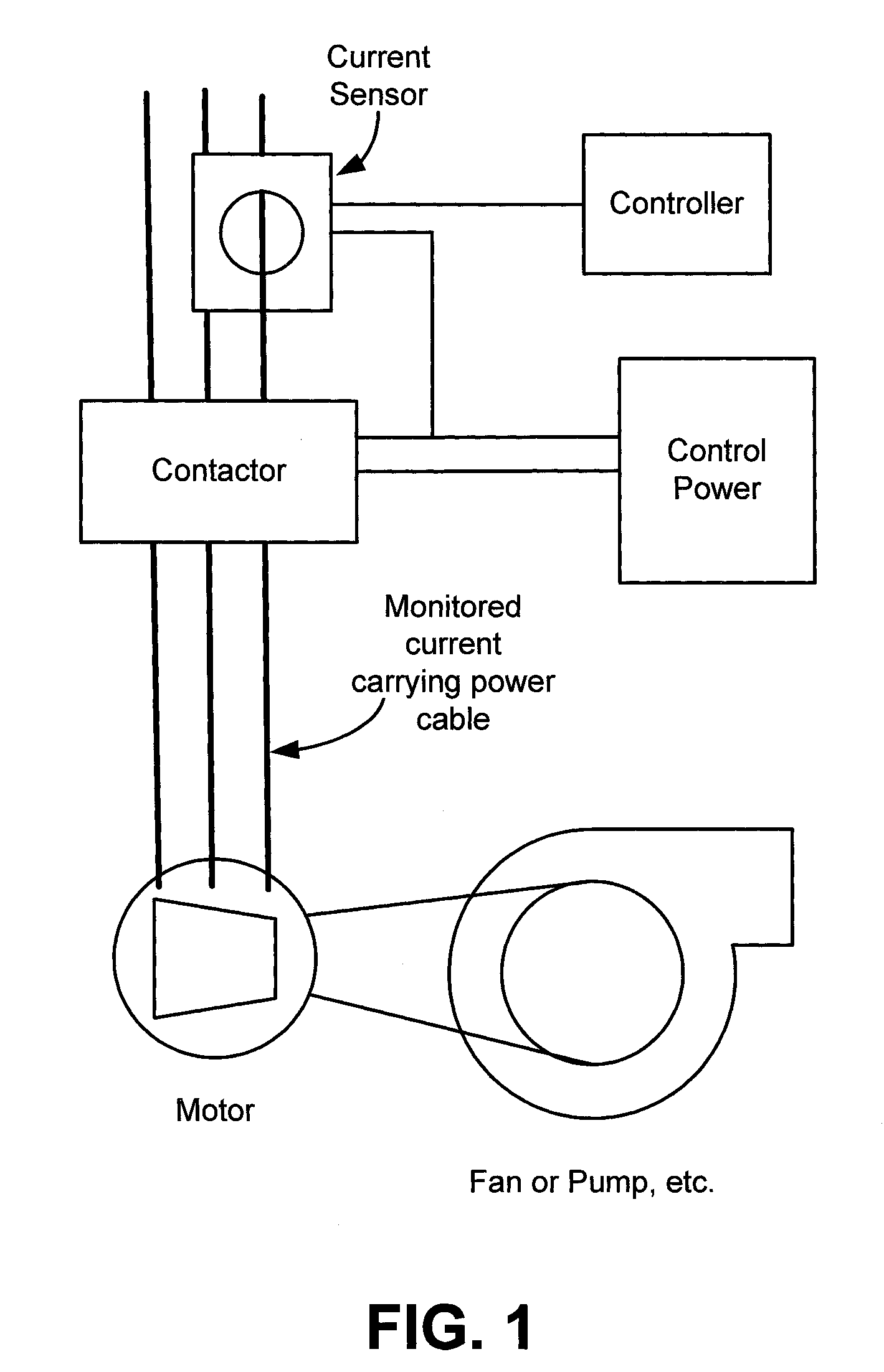
Image

Examples
Embodiment Construction
[0026]The following detailed description references apparatuses, systems, and methods embodying one or more principles of the invention consistent with the present application. It should be appreciated that the following embodiments are disclosed for illustrative purposes. The various components, structures, configurations, operating ranges, and / or other aspects of the disclosed embodiments are not meant to indicate limitations on the present invention. Those skilled in the relevant art will appreciate that the disclosed embodiments can be modified with fewer, additional, and / or alternative element without departing from the scope of the present invention.
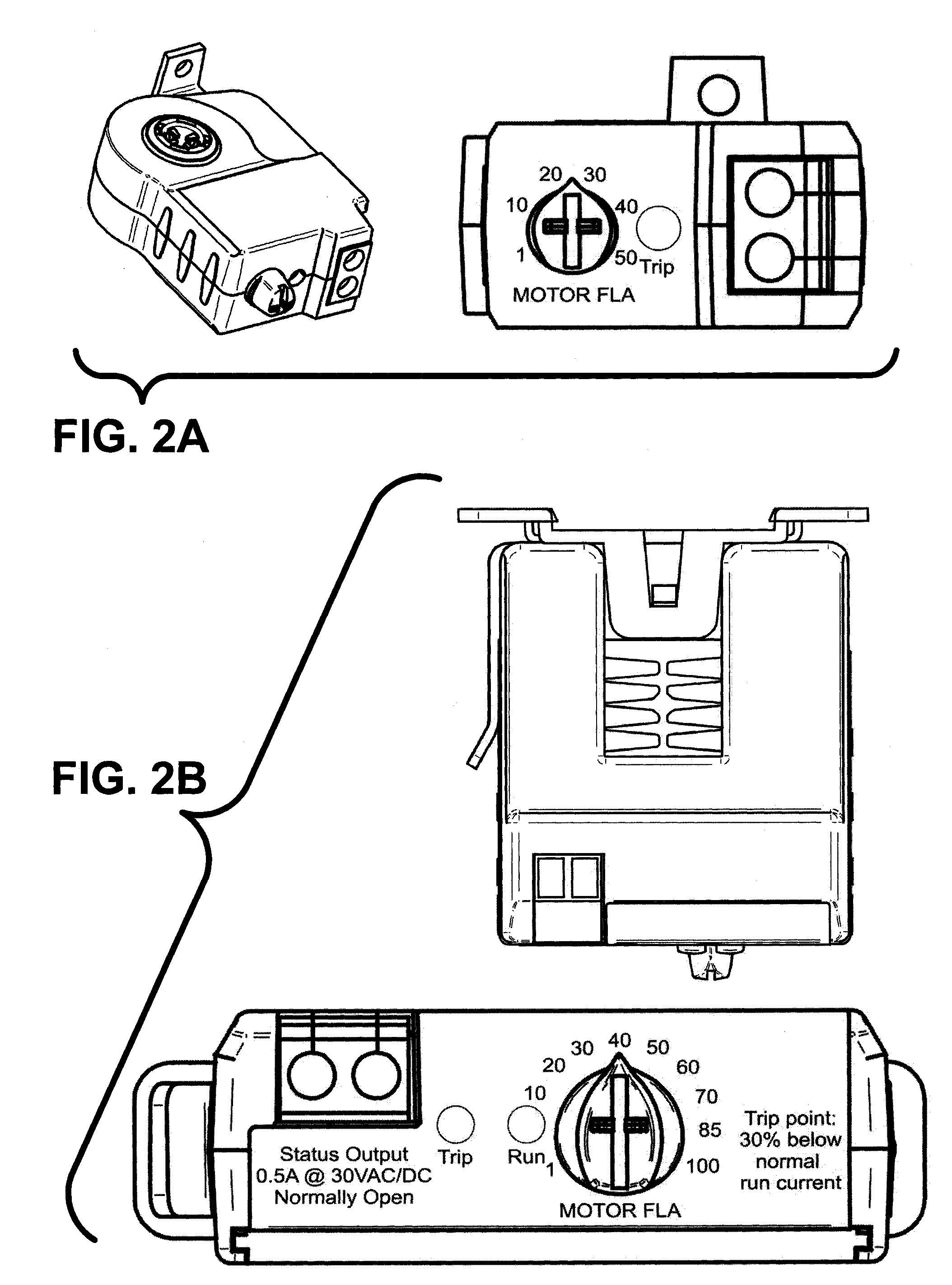
[0027]One embodiment can employ inventive circuitry design and / or components to provide improved current sensor devices that can have substantially simplified calibration procedures for initial installation and / or subsequent adjustment. For example, an embodiment can include a potentiometer (hereinafter “pot”) wired into a circuit ...
PUM
 Abstract
Description
Claims
Application Information