

Liquid crystal display apparatus and liquid crystal panel driving mehtod
a technology of liquid crystal display and liquid crystal panel, which is applied in the direction of instruments, computing, electric digital data processing, etc., can solve the problems of the above-mentioned liquid crystal display apparatus, and achieve the effect of restricting the polarization of liquid crystal molecules and impurities
- Summary
- Abstract
- Description
- Claims
- Application Information
AI Technical Summary
Benefits of technology
Problems solved by technology
Method used
Image

Examples
first exemplary embodiment
[0054]FIG. 7 is a block diagram generally showing the configuration of a liquid crystal display apparatus according to a first exemplary embodiment of the present invention. Referring to FIG. 7, main components of the liquid crystal display apparatus include video signal processing circuit 1, liquid crystal driving circuit 2, control unit 4, common voltage generator circuit 5, buffer 6, timer 8, liquid crystal panel 9, and storage unit 10.
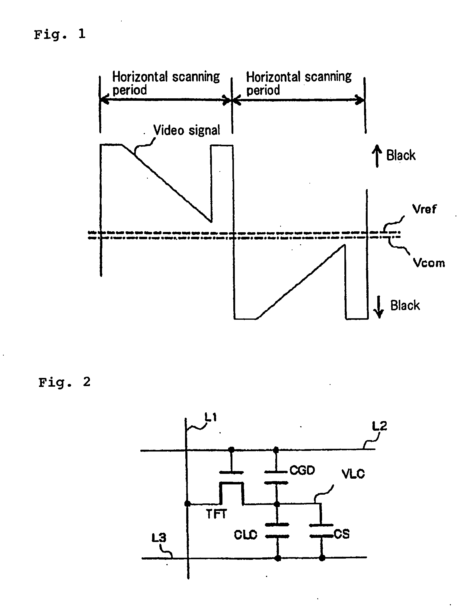
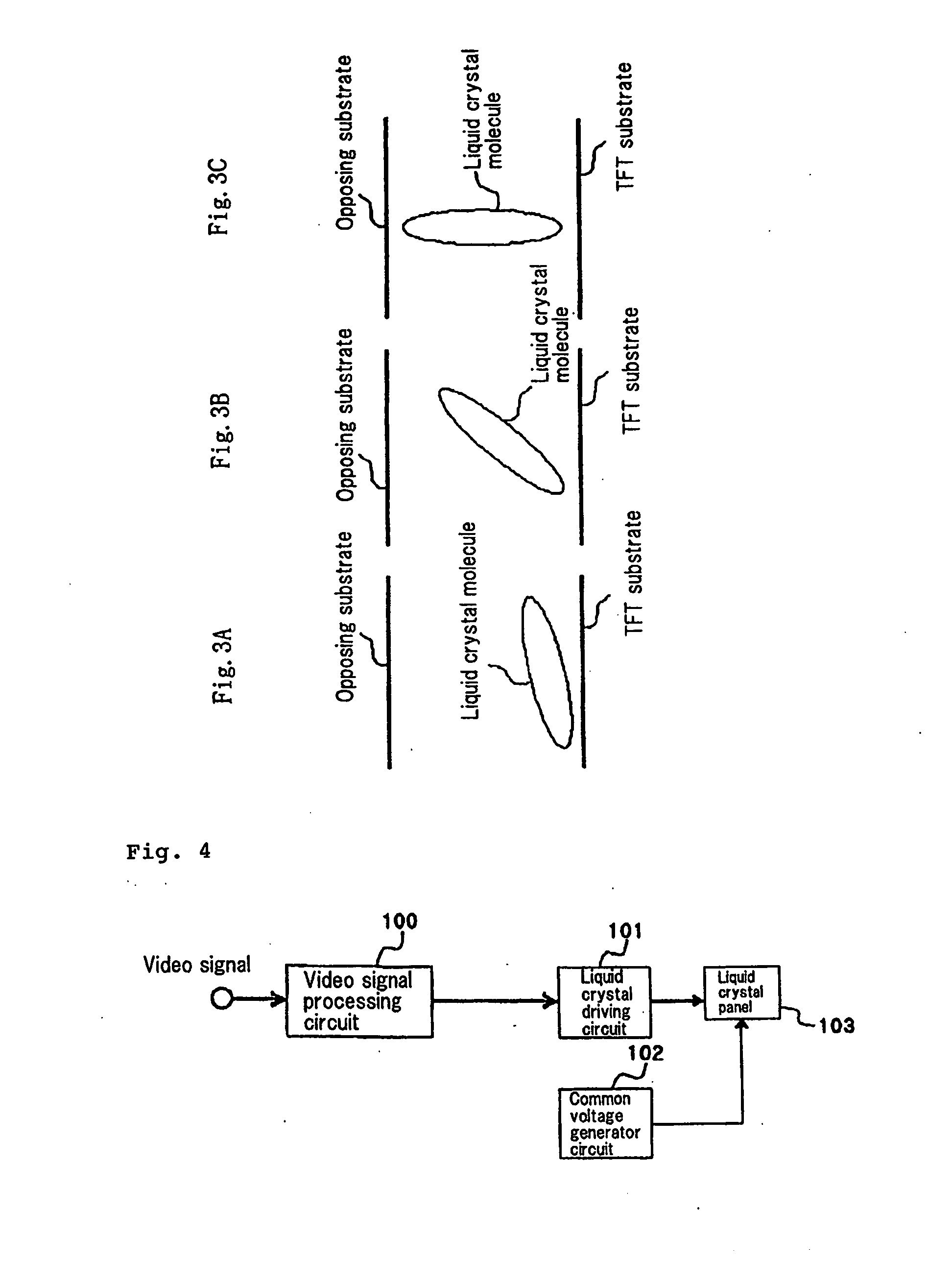
[0055]Liquid crystal panel 9 is an existing liquid crystal panel, and the same as the liquid crystal panel shown in FIG. 2, for example, can be used. Video signal processing circuit 1 performs processing for converting a video signal supplied from input terminal IN to a video signal suitable for display on liquid crystal panel 9, for example, scaling processing, frequency conversion processing and the like. Liquid crystal driving circuit 2 performs V-T correction processing, AC drive processing and the like on a video signal supplied from video sig...
second exemplary embodiment
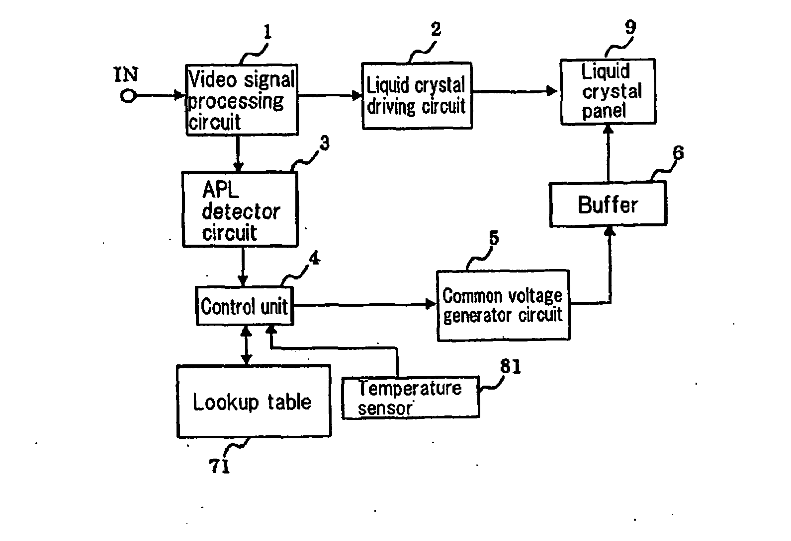
[0063]FIG. 8 is a block diagram showing the configuration of a liquid crystal display apparatus according to a second exemplary embodiment of the present invention. The liquid crystal display apparatus of this embodiment is basically the same as that illustrated in FIG. 7 in configuration except that temperature sensor 81 is provided instead of timer 8. In FIG. 8, the same components are designated with the same reference numerals. For avoiding repeated descriptions, in the following, a description on the same operation for the same component is omitted.
[0064]Storage unit 10 previously (e.g., in advance) stores characteristic data which represents the relationship between the temperature of liquid crystal panel 9 and an optimal value for a common voltage. Temperature sensor 81 detects the temperature of the liquid crystal display apparatus, and more preferably, the temperature near the liquid crystal panel. The output of temperature sensor 81 is supplied to control unit 4.
[0065]Cont...
third exemplary embodiment
[0069]FIG. 9 is a block diagram generally showing the configuration of a liquid crystal display apparatus according to a third exemplary embodiment of the present invention. The liquid crystal display apparatus of this exemplary embodiment includes video signal processing circuit 1, liquid crystal driving circuit 2, APL detector circuit 3, control unit 4, common voltage generator circuit 5, buffer 6, lookup table 7, timer 8, and liquid crystal panel 9. Video signal processing circuit 1, liquid crystal driving circuit 2, common voltage generator circuit 5, timer 8, and liquid crystal panel 9 are basically the same as those shown in FIG. 7. For avoiding repeated descriptions, in the following, a description on the same operation for the same component is omitted.
[0070]A video signal output from video signal processing circuit 1 is supplied to both liquid crystal driving circuit 2 and APL detector circuit 3. APL detector circuit 3 detects an average luminance level (average brightness)...
PUM
 Abstract
Description
Claims
Application Information