Method and system for high speed multi-pass inkjet printing

a multi-pass inkjet printing and high-speed technology, applied in the field of high-speed multi-pass inkjet printing, can solve the problems of insufficient multi-pass printing mode to improve print quality to an acceptable level, significant dot placement errors in the advancement direction of the nozzle located at the top and bottom of the printhead, and print quality defects, etc., to achieve the effect of fast print carriage speed and high speed

Active Publication Date: 2009-12-24
TELECOM ITALIA SPA +1
View PDF4 Cites 23 Cited by
  • Summary
  • Abstract
  • Description
  • Claims
  • Application Information

AI Technical Summary

Benefits of technology

[0012]The present invention relates to a high speed printing method to form an image in a plurality of printing passes, each pass corresponding to a swath. According to a preferred embodiment, the method comprises the step of generating print masks with a repetitive portion of mask columns consisting essentially of mask elements that disable pixel locations from being filled with ink dots. Such printing masks when applied to the input image data, create masked image data comprising data columns free of data, which can be removed to form print image data, thereby allowing a faster print carriage speed.

Problems solved by technology

This print mode is fastest, but it can result in print quality defects, particularly at swath boundaries.
In some types of printheads, it is common that nozzles located at the top and the bottom of the printhead exhibit significant dot placement errors in the advancement direction if compared to the nozzles at the central portion of the printhead.
A multi-pass printing mode can be Insufficient to improve print quality to an acceptable level, especially when specific groups of nozzles have worse errors than other groups of nozzles.

Method used


Image

  • Method and system for high speed multi-pass inkjet printing
  • Method and system for high speed multi-pass inkjet printing
  • Method and system for high speed multi-pass inkjet printing

Examples


example 1

[0061]A vertically interlaced multi-pass printing mode having N=3 and R=2 and using a printhead comprising at least a column of 129 writing nozzles (Z=129) is considered. An even print medium advance is considered, where m=1, 2, . . . , 6. The following three complementary print masks, {F1, F2, F3}, each of 129 rows, are defined:

F1=[100100100100100…100100100100100…100100100100100…………………………………………………………………………………100100100100100…100100100100100…100100100100100…](8)F2=[000………00010010010010010…10010010010010…10010010010010…………………………………………………………………………………………………………………………10010010010010…10010010010010…10010010010010…]F3=[000000………………0000001001001001001…1001001001001…1001001001001…………………………………………………………………1001001001001…1001001001001…1001001001001…]

[0062]With reference to Eq. (4), ω=(1,2,3,4,5,6). The vector representing the set of advances necessary to print the image bitmap is a={43,43,43,43,43,43}. By applying Eq. (7), the vector representing the mask indices, αm, is α={1,1,2,2,3,3}.

example 2

[0063]An interlaced multi-pass printing mode as that described in Example 1 is considered, with the difference that herein an uneven print medium advance sequence is selected. Three complementary print masks as those given in (8) are defined. A standard method of random shuffling selects vector ω to be ω={2,3,5,4,1,6}. From Eq. (4) and Eq. (7), the sequence of print medium advances and the sequence of mask indices is determined to be: a={44,43,44,41,39,37} and α={1,2,3,2,1,3}

[0064]One problem that comprises accurate dot placement is swath height errors of the inkjet printhead. Swath height errors are commonly produced by mechanical defects in the substrate of the printhead and can produce erroneous dot placement artifacts, such as ink drops are ejected at an angle to a printing medium rather than perpendicularly thereto. Since the majority of defective nozzles tend to be present mostly at the ends of the printhead, a way of reducing the effect of swath height errors, i.e., to minimi...

example 3

[0080]An Interlaced multi-pass printing mode having N=3 and R=2 and using a printhead comprising at least a column of 129 writing nozzles (Z=129) is considered. The number O of the nozzles of the end regions is 9. An even print medium advance is considered, where m=1, 2, . . . , 6. Three complementary print masks, {F1, F2, F3}, each of 129 rows, are defined and reported in FIG. 8. The 9 first rows and the last 9 rows of Fi (i=1, 2, 3) corresponding to the nozzles of the end regions of the printhead contribute only to a shingling mode N+1, while the remaining 111 rows contribute to both shingling modes N and N+1.

[0081]With reference to Eq. (4), ω={1,2,3,4,5,6}. By applying Eq. (9) the vector representing the set of advances necessary to print the image bitmap is a={40,40,40,40,40,40}. By applying Eq. (7), the vector representing the mask indices, αm, is α={1,1,2,2,3,3}.

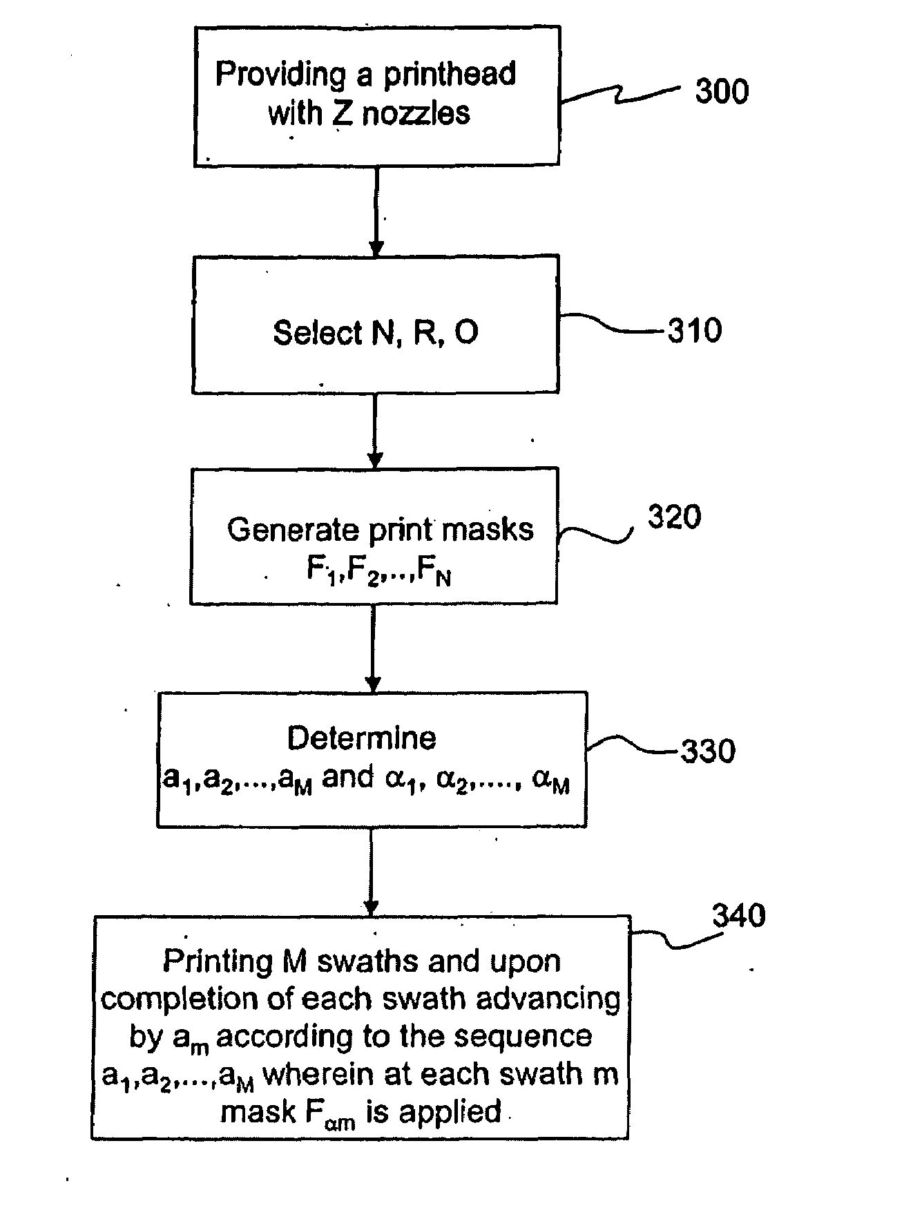
[0082]FIG. 9 is a flow chart of a method of printing ink drops configured to form an image bitmap on a print medium ...


PUM


Abstract

A method of printing from a printhead includes virtually dividing a nozzle array of the printhead into first and second nozzle sections. N print masks associated with the first and second nozzle sections govern the deposition of ink drops on a print medium. The N print masks are associated with one swath and are defined as a mask grid. The mask grid is arranged as a series of vertically extending adjacent mask columns and a series of horizontally extending mask rows. The vertically extending mask columns comprise enabling mask columns comprising first mask elements and disabling mask columns consisting essentially of second mask elements. The N print masks are associated with the first and second nozzle sections for printing an input image. Each print mask is defined as a mask grid arranged in an N series of vertically extending adjacent mask columns and a series of Z horizontally extending mask rows. The series of mask rows are divided in first and second adjacent mask sections corresponding to the first and second nozzle sections, respectively. The mask rows of the second mask section are arranged spaced from one another by N−1 adjacent second mask elements and the mask rows of the first nozzle section are arranged spaced from one another by 2N−1 adjacent second mask elements within the same mask row

Description

FIELD OF THE INVENTION[0001]This invention generally relates to a system and a method for printing of text or graphics on printing media such as paper or other glossy media, such as photo-quality paper.BACKGROUND OF THE INVENTION[0002]Ink jet printers commonly include one or more printheads which are mounted on a carriage assembly. The carriage assembly is moveable in a transverse direction (generally perpendicular) relative to an advance direction of a print medium such as paper. As the printhead moves across the surface of the print medium during a particular pass, ink is selectively ejected from a plurality of nozzles pursuant to commands from a microcomputer or other controller and deposited on the print medium at corresponding ink dot placement locations, called pixels, in the image of the print medium. The image created from individual ink dots on the printing medium result in a two-dimensional pixel array, which can be referred to as the image bitmap.[0003]Many conventional h...

Claims


Application Information

Patent Timeline
Patent Type & Authority Applications(United States)
IPC IPC(8): B41J29/38
CPCG06K15/107
Inventor DIMITRIJEVIC, ANACATTARINUSSI, SERGEBAROUD, TAHA
Owner TELECOM ITALIA SPA
Why Eureka
Try Eureka