
Dual emission microscope

a microscope and dual-emission technology, applied in the direction of optical radiation measurement, instruments, polarising elements, etc., can solve the problems of aberration and distortion, aberration and distortion, etc., and achieve the effect of simple and compact design

Active Publication Date: 2009-12-24
TILL I D
View PDF7 Cites 14 Cited by
  • Summary
  • Abstract
  • Description
  • Claims
  • Application Information

AI Technical Summary

Benefits of technology

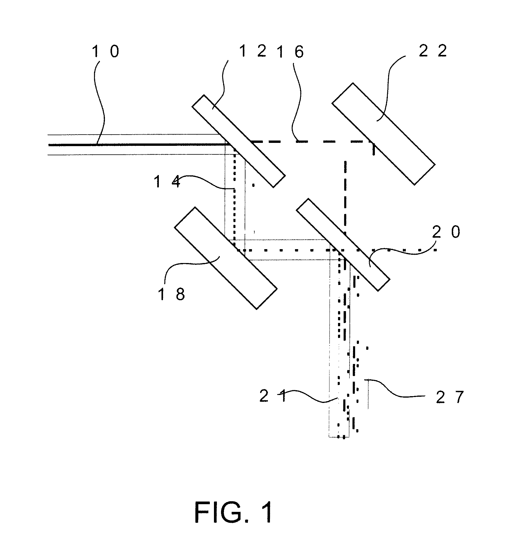
[0013]According to the microscope device defined in claim 1 or 25, each color / polarisation channel undergoes at least one additional reflection after having been separated from the other color / polarisation channel. This concept enables comfortable adjustment of the position of each of the color / polarisation channels on the camera-chip.
[0014]According to the microscope device as defined in claim 16 or 26, only one of the color / polarisation channels undergoes additional reflections after having been separated from the other color / polarisation channel, while for the other color / polarisation channel the reflection needed for separating and reuniting the two beams remains the only reflection. Thereby a particularly simple and compact design can be achieved. According to a preferred embodiment, the means for reflecting the second beam and the separating means are integrated within a single member.

Problems solved by technology

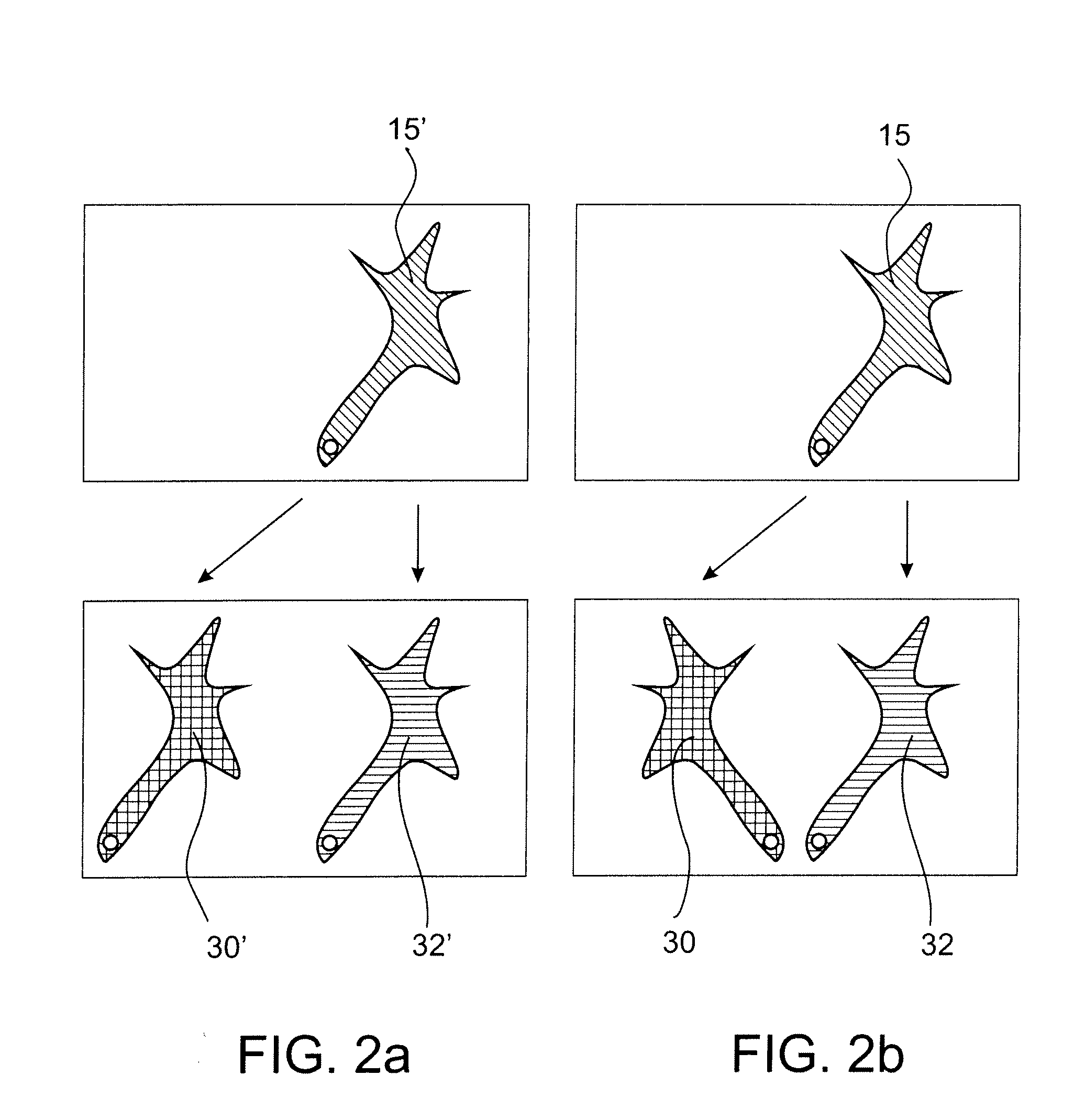
However, since no optical system is perfect, there are always aberrations and distortions, and their extent depends on the position of a given point within the field.
However, due to the spherical symmetry of the imaging optics, aberrations and distortions are generally symmetrical with respect to the central axis of the optics.

Method used


Image

  • Dual emission microscope
  • Dual emission microscope
  • Dual emission microscope

Examples


Embodiment Construction

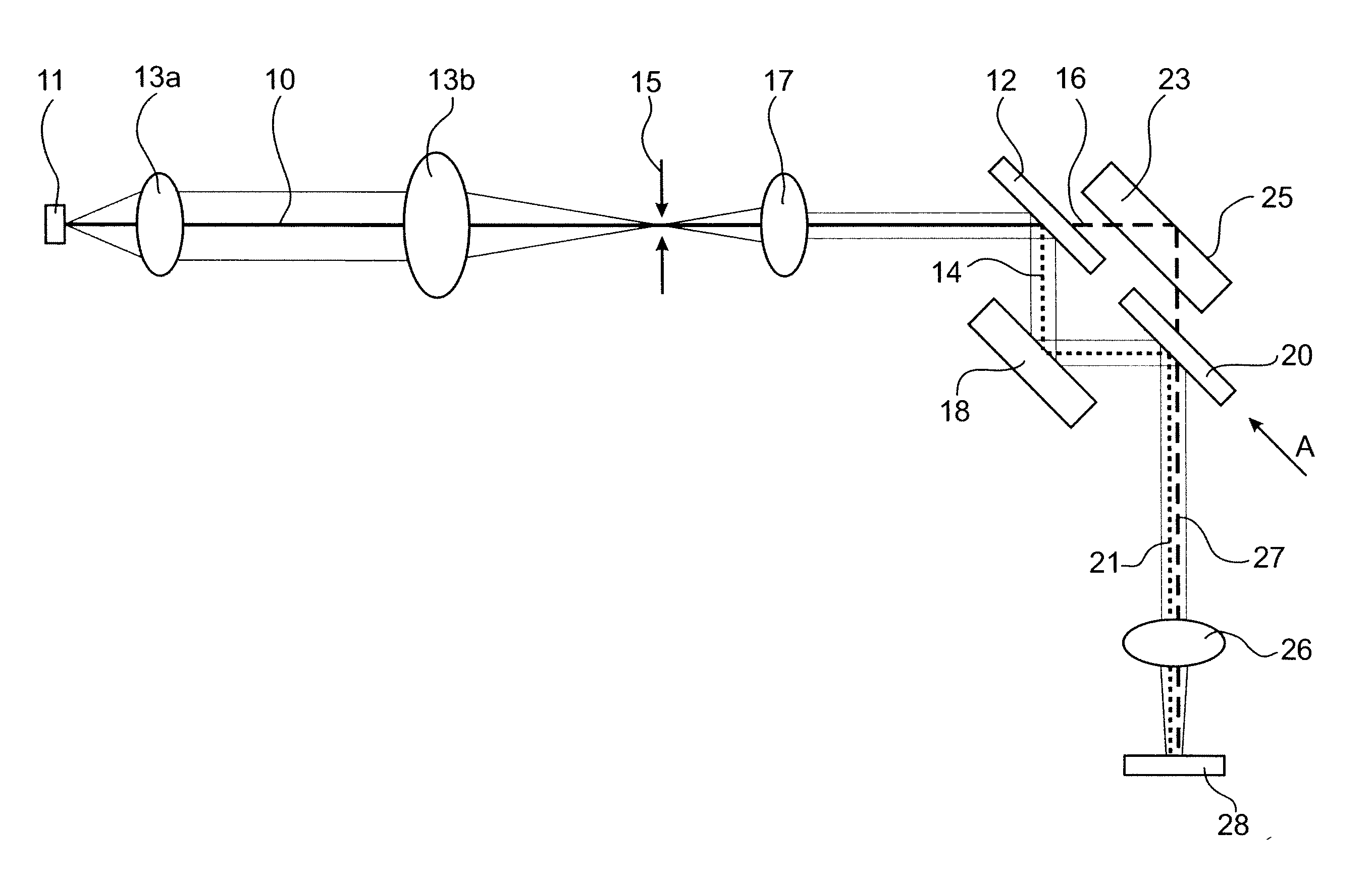
[0025]FIGS. 3a and 3b show a first embodiment of a microscope device according to the invention, wherein a collimated multi-color beam 10 is generated by collecting light from a sample 11 by a compound microscope 13 (in the drawing consisting of objective 13a and tube lens 13b). The microscope creates an intermediate image 15 located in the focal plane of a projection lens 17. Typically, the light collected from the sample 11 will be emission light, in particular fluorescence emission light, such as emission light obtained from Fluorescence Resonance Energy Transfer (FRET). A first dichroic beamsplitter 12 serves to reflect one wavelength component of the beam 10 (if the dichroic is a long-pass, beam 14 is the short-wavelength-part of beam 10) toward a mirror 18, thereby generating a first beam 14, whereas the component of the beam 10, which is transmitted by dichroic 12, constitutes a second beam 16, which is directed towards a roof prism 23. While the first beam 14 is reflected by...


PUM


Abstract

There is provided a microscope device comprising: means for creating a collimated beam of light collected from a sample and comprising at least a first spectral range and a second spectral range, means for separating the collimated beam into a first beam containing a higher percentage of light of the first spectral range than light of the second spectral range and a second beam containing a lower percentage of light of the first spectral range than light of the second spectral range, means for reflecting the first beam, means for reflecting the second beam, means for combining the first beam and the second beam, a detector, and means for imaging the combined first and second beam onto the detector in order to create an image of the sample on the detector, wherein the means for reflecting the first beam and the means for reflecting the second beam are arranged in such a manner that the image created by the first beam and the image created by the second beam are shifted relative to each other on the detector, wherein the means for reflecting the first beam is adapted to invert handedness of the first beam, and wherein the means for reflecting the second beam is adapted to preserve handedness of the second beam.

Description

BACKGROUND OF THE INVENTION[0001]1. Field of the Invention[0002]The present invention relates to a microscope device, which is capable of producing images of a sample in different spectral ranges (“colors”) or polarisations on a single detector.[0003]2. Description of Related Art[0004]In 1991 a method for separating a microscope image into two images of different color placed next to each other on a single camera chip was proposed (K. Kinosita et al., “Dual-View Microscopy with a Single Camera: Real-Time Imaging of Molecular Orientations and Calcium”, J. Cell. Biol., 1991, 115(1), pages 67-73); see also U.S. Pat. No. 5,337,081). The commercial version of this concept was termed “w-View” because it not only provides a “double view” of the sample, but also because of the w-shape of the beam path it employs. (http: / / jp.hamamatsu.com / resources / products / sys / pdf / eng / e_aqfret.pdf). The design is used in all fields of microscopy where dual-emission images need to be recorded. Given that it ...

Claims


Application Information

Patent Timeline
IPC IPC(8): G02B21/06G02B21/18G02B21/02
CPCG02B17/026G02B21/18G02B21/16G02B21/0092
Inventor UHL, RAINER
Owner TILL I D
Learn More