
Device for characterizing unique objects

a unique object and device technology, applied in the field of characterization, can solve the problems of destructive and not very fast approach, time-consuming, restricted technique,

Inactive Publication Date: 2009-12-24
COMMISSARIAT A LENERGIE ATOMIQUE ET AUX ENERGIES ALTERNATIVES
View PDF13 Cites 22 Cited by
  • Summary
  • Abstract
  • Description
  • Claims
  • Application Information

AI Technical Summary

Benefits of technology

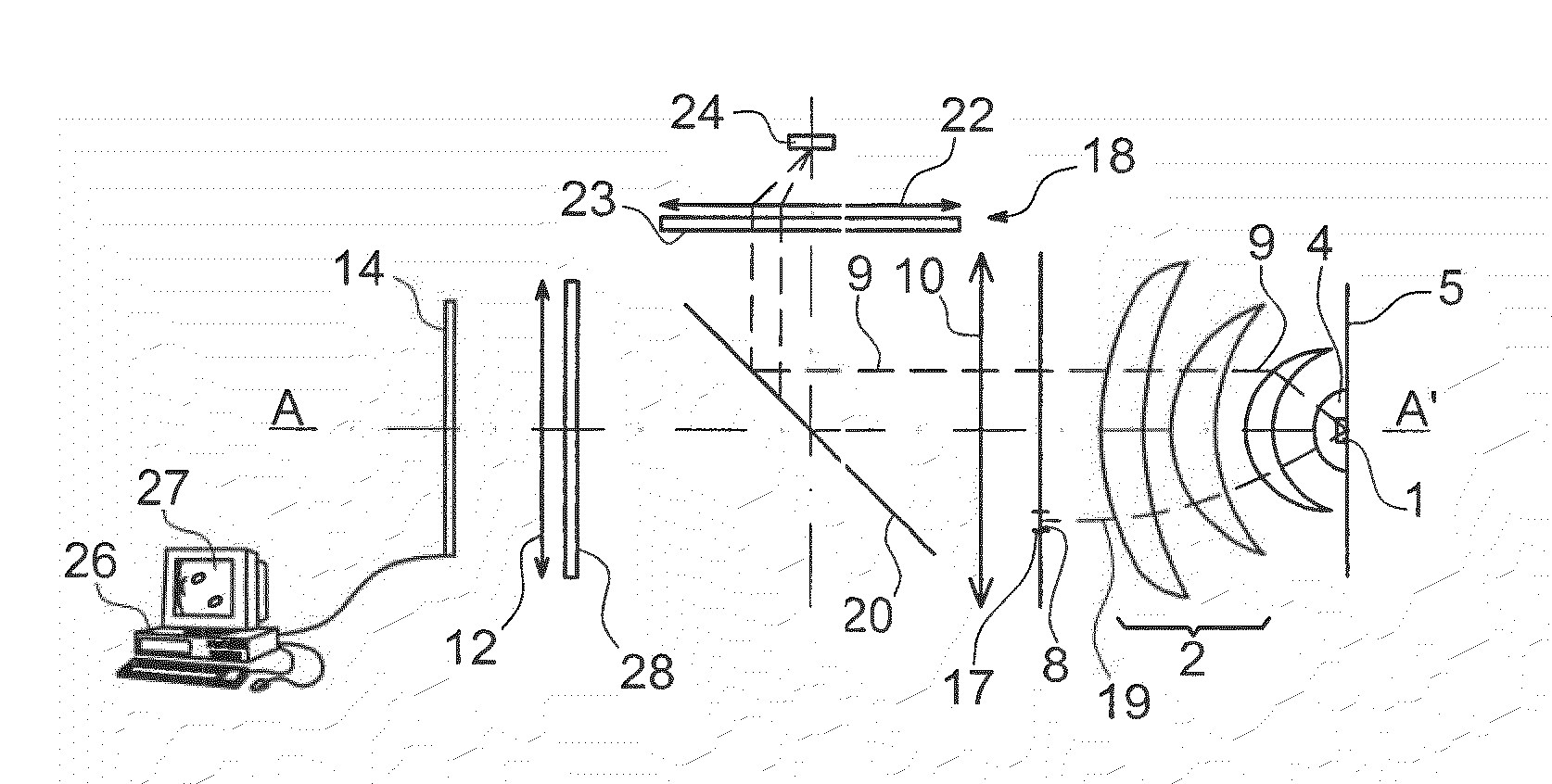
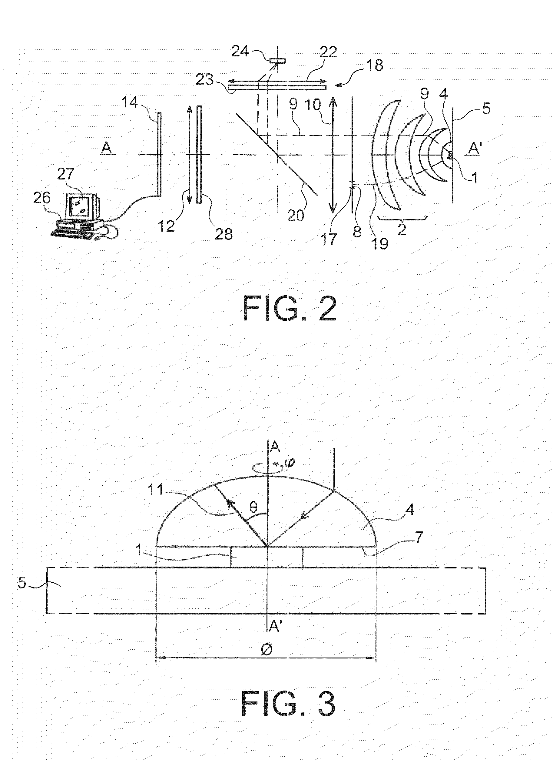
[0019]This combination between a coherent source and high numerical aperture focussing means makes it possible to produce all the incidences on the object simultaneously. With the maximum aperture, or with a high aperture, work is performed on a very small zone of the object and the surrounding substrate. In this way, this avoids having to use means to select a specific incidence.
[0031]It is possible to eliminate the “speckle” phenomenon, inherent to coherent light, by moving the object in translation, along the optical axis of the device, with reference to the optical system or with respect to the lens close to the object, which induces a phase rotation of the Fourier transform and scrambling of the speckle. The distance between the object and the focussing means is varied; or the distance, between the object and at least one part of the focussing means, remains fixed, and the distance between, on one hand, the assembly of the object and at least one part of the focussing means and, on the other, at least the coherent source and the detection means is varied. It is also possible to move the object in the object plane, which may be an oscillating movement in the object plane, of an amplitude less than one micrometre.

Problems solved by technology

This approach has the drawback of being destructive and not very fast.
Similarly, the AFM (atomic force microscope) technique, although it is non-destructive, is time-consuming.
This technique is restricted by the data acquisition time which requires the mechanical movement of the detectors.
Although the scaterometry technique has proved its merits and is used on a daily basis, it is confronted with the need to produce specific characterisation patterns, forming gratings, which, on one hand, occupy a specific position on the wafers or the substrates and, on the other, cannot be placed in any position.
This is a problem in that, conversely, it is increasingly desired to increase the occupancy rate of the surface of each substrate.
In addition, the problem arises of finding a method that can be implemented in all the zones or all the parts of a substrate.
The problem also arises of being able to identify the presence and the shape of any pattern on the surface of a substrate.

Method used


Image

  • Device for characterizing unique objects
  • Device for characterizing unique objects
  • Device for characterizing unique objects

Examples


Embodiment Construction

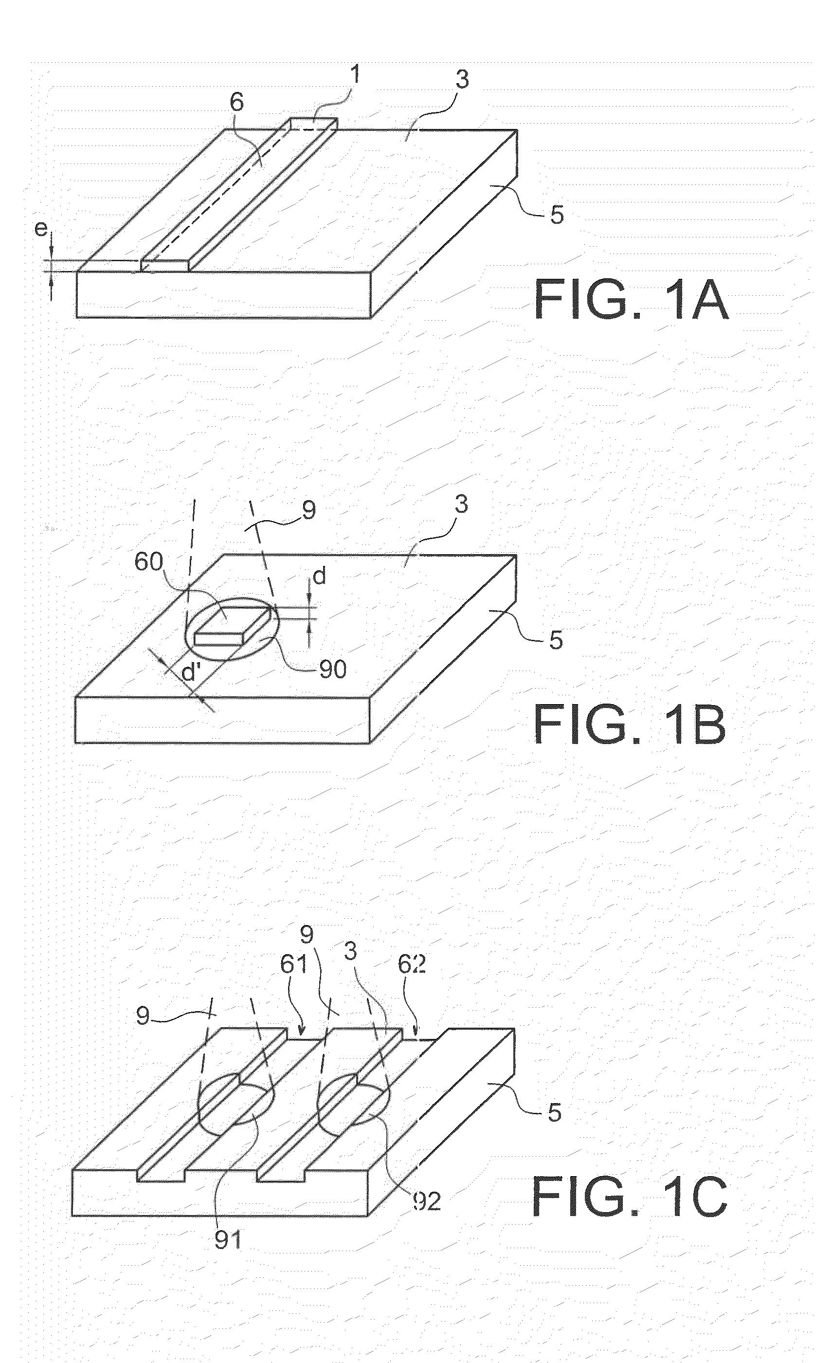
[0013]The invention relates to a new scaterometry technique, which makes it possible to make measurements on so-called “unique” objects. These may be lines or contact blocks that can be found at any point on a surface of a substrate and which result from the implementation of a microtechnology or microelectronic method. Said lines or contact blocks do not need to be specifically provided for, unlike the characterisation grids used in techniques according to the prior art.

[0014]According to the invention, the infinite diffraction figure generated by such a unique object is observed by means of an optical system. An examination method according to the invention comprises:

[0015]the illumination of the object, and of a part of a substrate whereon it is formed, by means of a spatially coherent light beam, preferentially from a directive source optical system, focussed on the object with a high numerical aperture,

[0016]the formation of the image of the optical FT (Fourier transform) of th...


PUM


Abstract

An examination method of a unique object including: forming a coherent radiation beam using a coherent source, illuminating the object by the coherent radiation beam, focussed using a focussing mechanism positioned directly in contact with the object or in a very close position to the object, and forming, using a detection mechanism, the optical Fourier transform image of the light diffracted by the object.

Description

FIELD OF THE INVENTION AND STATE OF THE RELATED ART[0001]The invention relates to the field of characterisation—particularly applied for the purposes of microelectronics—which makes it possible to determine the shapes of patterns on the surface of a substrate. This technique enables characterisation on a so-called “unique” isolated object.[0002]Lithography, combined with deposition and etching techniques, makes it possible to “transfer”, by means of an optical process, the image of a mask, whereon patterns are represented, in a resin deposited on the very surface of substrates. The resin, once insolated, is developed and generally serves as a mask for etching and / or deposition processes used to carry out integrated circuit production steps.[0003]The quality of photoetching methods is tested, in production lines, by means of various referenced characterisation methods such as “Critical Dimension Metrology”. It is endeavoured to measure nanometric dimensions (up to 100 nm) with precis...

Claims


Application Information

Patent Timeline
IPC IPC(8): G06K9/00G01B11/24
CPCG01B11/24H01L22/12G03F7/70625G01N21/9501
Inventor GIDON, SERGE
Owner COMMISSARIAT A LENERGIE ATOMIQUE ET AUX ENERGIES ALTERNATIVES
Learn More