
Method for Filtering of Images with Bilateral Filters and Power Images

a filtering method and filtering technology, applied in image enhancement, image analysis, instruments, etc., can solve the problems of loss of precision, computational complexity, and impracticality of even moderate filter radii, and achieve the effect of not increasing complexity

Inactive Publication Date: 2009-12-24
MITSUBISHI ELECTRIC RES LAB INC
View PDF4 Cites 17 Cited by
  • Summary
  • Abstract
  • Description
  • Claims
  • Application Information

AI Technical Summary

Benefits of technology

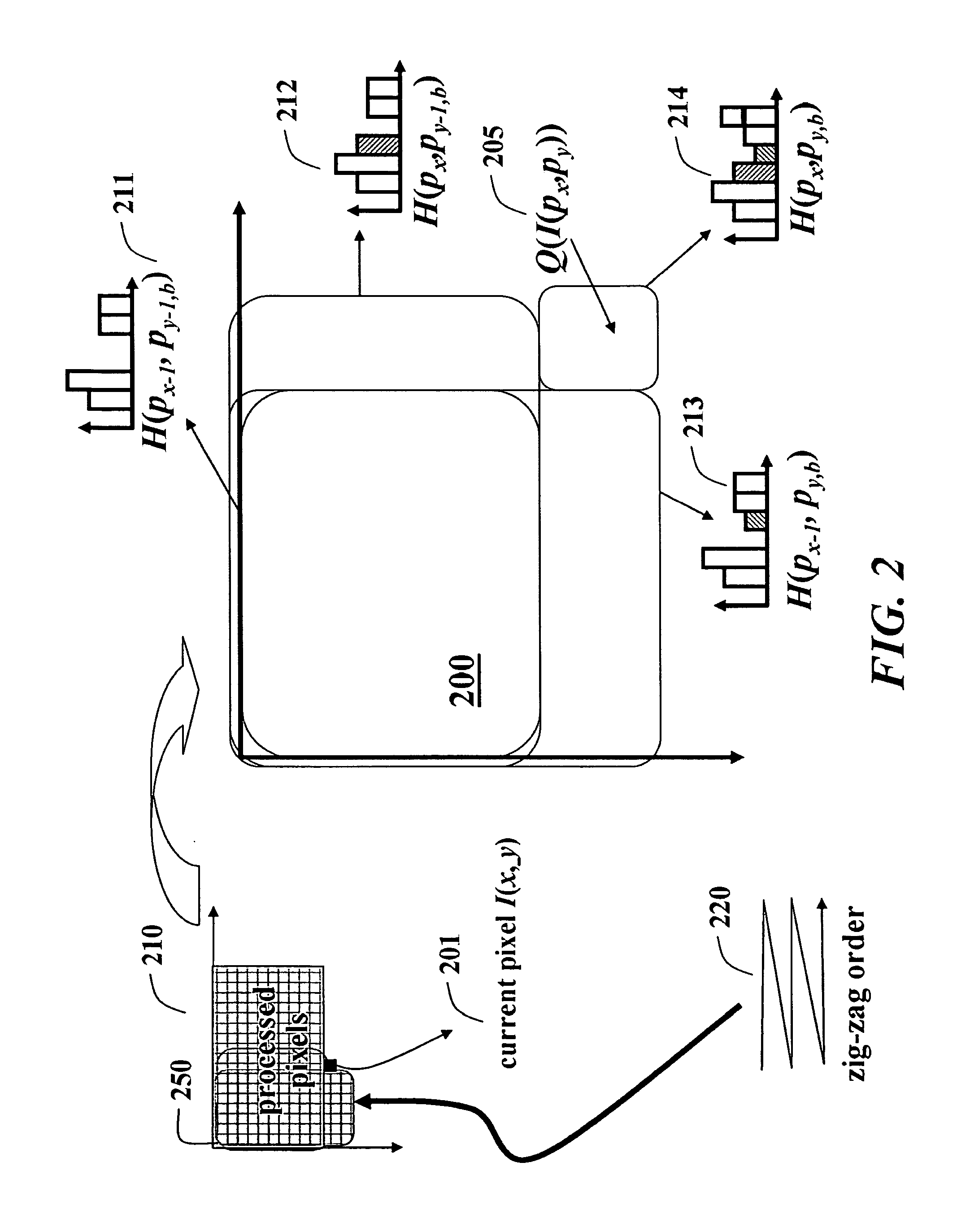
[0009]One embodiment of the invention takes advantage of integral histograms to avoid the redundant operations for bilateral filters with spatial and range kernels.
[0012]All these embodiments drastically decrease the processing time to a constant time, e.g., to 0.3 seconds per 1 MB image, while achieving very high peak signal-to-noise ratio (PSNR) greater than 45 dB. In addition to the computational advantages, our methods are straightforward to implement.
[0013]It is believed that the present filtering method is the most efficient bilateral filter yet developed. This means that the method performs better than those of higher complexities as the kernel radius increases. Given the trend toward higher-resolution images, which correspondingly require larger kernel radii, filtering with large kernels as fast as with the small kernels makes the method advantageous.
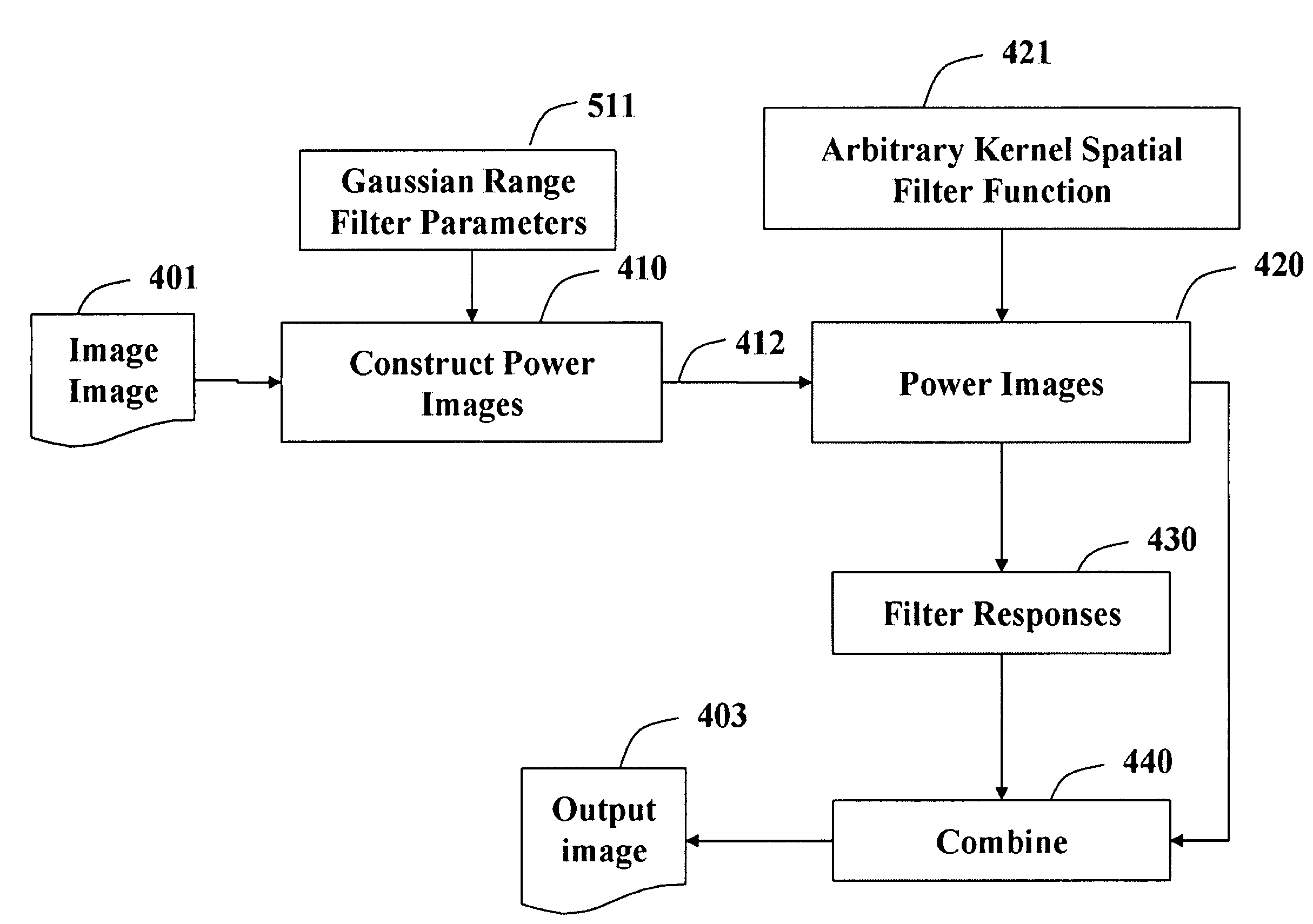
[0016]For more generic Gaussian and polynomial range functions on arbitrary domain kernels, Taylor series expansion of the corresponding norms is used. This enables the use of “any” spatial kernel for bilateral filtering without increasing the complexity. Such bilateral filters can be expressed in terms of spatial linear filters applied to power images.

Problems solved by technology

Due to the joint spatial and range filtering, the bilateral filters are computationally demanding.
For reference, a brute-force implementation can calculate each output pixel in exponential O(r2) time and becomes impractical for even moderate filter radii.
However, the discretization leads to loss of precision, particularly in high dynamic range (HDR) images.
Even though the complexity has been lowered, simplicity has been lost due to the relatively small filter size and histogram count specific implementation requirements.
That method is limited to rectangular spatial kernels and box filters.

Method used


Image

  • Method for Filtering of Images with Bilateral Filters and Power Images
  • Method for Filtering of Images with Bilateral Filters and Power Images
  • Method for Filtering of Images with Bilateral Filters and Power Images

Examples


Embodiment Construction

[0022]Bilateral Filtering

[0023]A filter f is a mapping defined in a d-dimensional Cartesian space Rd. The filter assigns an m-dimensional response vector (response) y(p)=[y1, . . . , ym] to each pixel p=[x1, . . . , xd] of an input image I bounded within N1, . . . , Nd and 0≦xii.

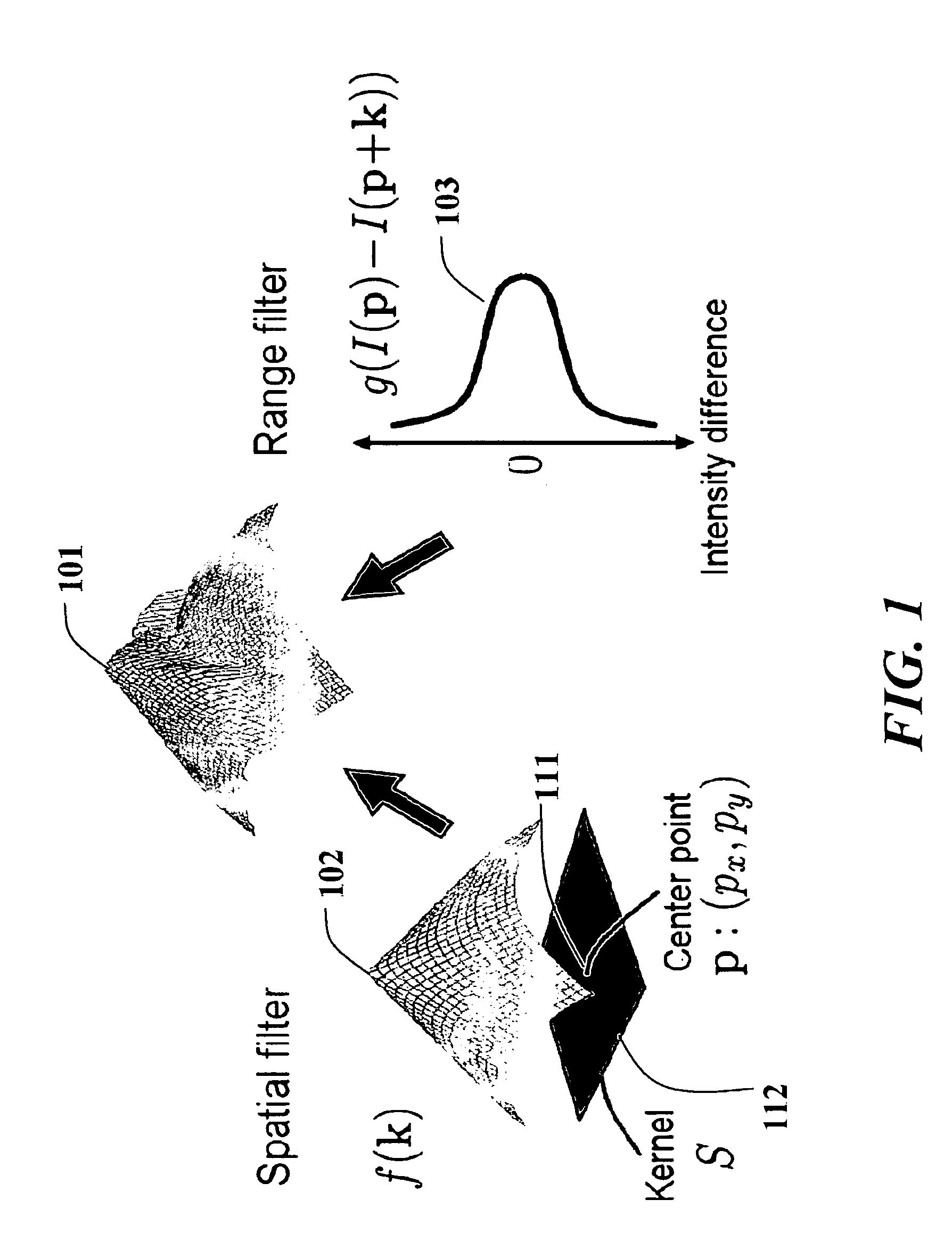
[0024]Generally, only a small set of pixels within a region of support S is used to determine the filter response. The region of support, which is centered around the pixel p, is called the filter footprint or kernel. Without loss of generality, the set of pixels maps to a scalar value, i.e., m=1 and y(p)=y1. An example embodiment uses single channel image filtering (d=2, m=1). However, the method can be extended to higher dimensions, color images and temporal video filtering.

[0025]A 2D image filter centered at the image pixel p applies its coefficients f(k) to the values of the underlying image pixels k+p within its kernel k=[kx, ky]∈ S.

[0026]For rectangular kernels, the coordinate of the center pixel can b...


PUM


Abstract

The current invention describes a method for filtering an input image with a bilateral filter. The bilateral filter includes a spatial filter and a range filter. The method constructs a set of power images from an input image including pixels, each pixel having intensity. Then, the method applies, to each power image, the spatial filter to determine a response for the spatial filter and the corresponding power image and combines the responses and the set of power images to produce a response for the bilateral filter.

Description

FIELD OF THE INVENTION[0001]The present intention relates generally to filtering images, and more particularly to filtering images with bilateral filters in constant O(1) time.BACKGROUND OF THE INVENTION[0002]A bilateral filter is a non-linear filter applied to an image in the spatial and intensity domain. A fast bilateral filter is important for many computer vision applications. Several methods are known for decomposing non-linear filters into separable one-dimensional filters, or cascaded representations to reduce processing time. This can be done by using of either an eigenvalue expansion of the 2D filter kernel, or application of a singular value decomposition (SVD). A number of methods aim to benefit from the parallel processing and reconfigurable hardware.[0003]The bilateral filter is a non-iterative means for smoothing images while retaining edge detail. The filtering involves a weighted convolution, wherein the weight for each pixel depends not only on its distance from the...

Claims


Application Information

Patent Timeline
IPC IPC(8): G06K9/40
CPCG06T2207/20028G06T5/20
Inventor PORIKLI, FATIH M.
Owner MITSUBISHI ELECTRIC RES LAB INC
Learn More