Optical fiber and optical fiber preform

Active Publication Date: 2009-12-24
THE FUJIKURA CABLE WORKS LTD
View PDF5 Cites 6 Cited by
  • Summary
  • Abstract
  • Description
  • Claims
  • Application Information

AI Technical Summary

Benefits of technology

[0023]The invention is designed to solve the above-mentioned problems. An object of the invention is to provide an optical fiber and an optical fiber preform which have stable character

Problems solved by technology

However, there was a problem in that only a predetermined intensity of light (SBS threshold power) can be transmitted through the optical fiber although higher power is

Method used


Image

  • Optical fiber and optical fiber preform
  • Optical fiber and optical fiber preform
  • Optical fiber and optical fiber preform

Examples


examples 1a to 1g

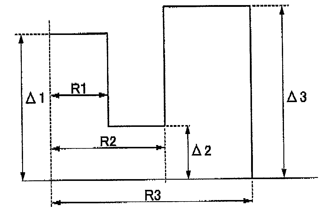
[0085]Table 3 shows results in the case where structural parameters of Example 1 are represented by using X, Y, and R2 / R1 described above.

TABLE 3UnitExample 1aExample 1bExample 1cExample 1dExample 1eExample 1fExample 1gR1μm1.531.501.351.261.161.031.03R2μm2.913.292.983.152.913.213.20R3μm4.444.794.344.414.084.244.24R2 / R1—1.92.22.22.52.53.13.1Δ1%0.500.500.400.600.300.500.60Δ2%0.050.200.200.200.200.200.20Δ3%0.500.400.500.500.600.600.60Δ1 −Δ2%0.450.300.200.400.100.300.40Δ3 −Δ2%0.450.200.300.300.400.400.40Δ3 + Δ2%0.550.600.700.700.800.800.80Fiber cutoffμm1.321.321.321.321.321.321.32WavelengthCable cutoffμm1.241.241.241.241.241.241.24wavelengthMFD(Petermann II)μm9.479.569.489.119.229.459.27at 1.31 μmZero-dispersionnm1321.61314.313091321.11323.71314.71317.3wavelengthZero-dispersionps / nm2-km0.090.09070.08920.08990.08950.08950.0893slope20 mm diameterdB / m0.390.190.240.070.300.300.16bending lossat 1.31 μmSBS thresholddBm13.113.112.513.312.413.212.9at 1.55 μm 20 km

[0086]The optical fibers having...

examples 1h to 1v

[0087]Tables 4 and 5 show results in the case where structural parameters of Example 1 are represented by using X, Y, and R2 / R1 described above. The optical fibers having the structural parameters of Examples 1 a to 1g shown in Table 3 and Examples 1h to 1v shown in Tables 4 and 5 had SBS thresholds of 10.9 to 13.8 dBm for a length of 20 km as shown in FIG. 14 and could obtain suppression effects higher than the SMF having the same MFD by +3.1 to +4.5 dB. In addition, the optical characteristics of the optical fibers of Examples 1h to 1v all satisfied the G652 standard.

TABLE 4UnitExample 1hExample 1iExample 1jExample 1kExample 1lExample 1mExample 1nR1μm1.811.693.141.332.801.121.74R2μm2.903.215.813.335.333.486.80R3μm4.714.908.954.678.134.608.54R2 / R1—1.61.91.92.51.93.13.9Δ1%0.500.500.500.500.400.500.60Δ2%0.100.100.200.100.200.200.20Δ3%0.400.400.400.500.500.500.60Δ1 −Δ2%0.400.400.300.400.200.300.40Δ3 −Δ2%0.300.300.200.400.300.300.40Δ3 + Δ2%0.500.500.600.600.700.700.80Fiber cutoffμm1.32...

examples 2a to 2f

[0088]Table 6 shows optical characteristics in the case where structural parameters of a refractive index profile of the optical fiber having the refractive index profile of FIG. 6 are represented by using X, Y, and R2 / R1 described above.

TABLE 6UnitExample 2aExample 2bExample 2cExample 2dExample 2eExample 2fR1μm1.511.391.431.311.111.33R2μm3.033.052.873.133.103.45R2μm4.604.494.364.494.254.83R2 / R1%2.002.202.002.402.802.60Δ1%0.500.500.440.560.440.40Δ2%0.240.220.180.180.260.30Δ3%0.500.600.700.700.700.70Δ1 −Δ2%0.260.280.260.380.180.10Δ3 −Δ2%0.260.380.520.520.440.40Δ3 + Δ2%0.740.820.880.880.961.00Fiber cutoffμm1.321.321.321.321.321.32wavelengthCable cutoffμm1.241.241.241.241.241.24wavelengthMFD(Petermann II)μm9.29.369.449.399.379.1at 1.31 μmZero-dispersionnm1317.91314.91314.21322.61309.51308.1wavelengthZero-dispersionps / nm2-km0.09060.09050.09020.09140.08970.0898slope20 mm diameterdB / m0.390.691.421.350.920.15bending lossat 1.31 μmSBS thresholddBm12.012.813.013.712.312.0at 1.55 μm

[0089]The ...


PUM


Abstract

An optical fiber is constituted by: a three-layer structured core which includes, a first core (having a relative refractive index difference of Δ1 in a region of a radius of R1), a second core (having a relative refractive index difference of Δ2 in a region from the radius R1 to a radius of R2), and a third core (having a relative refractive index difference of Δ3 in a region from the radius of R2 to a radius of R3), wherein the relative refractive index differences have relationships of Δ1>Δ2, Δ3>Δ2, and Δ3>Δ1, when Δ1−Δ2=X and Δ3−Δ2=Y, (X+Y)>0.4% is satisfied, and X and Y satisfy 0.25%<X<0.6%, 0.1%≦0.6%, and a relationship of (2*X−0.7)%<Y<(X/2+0.4)%, thereby satisfying the G652 standard and having an SBS threshold equal to or higher than that of an optical fiber having the same MID by +3 dB or higher.

Description

TECHNICAL FIELD [0001]The present invention relates to an optical fiber and an optical fiber preform. There was a problem in that when an optical analog signal or an optical baseband signal is transmitted for a long distance by using an optical fiber, due to an effect of stimulated Brillouin scattering (hereinafrer, referred to as SBS), only a predetermined intensity of light (SBS threshold power) can be transmitted through the optical fiber although light with higher power was intended to be transmitted, and the remaining light becomes backscattered light and returns to the incoming side, so that transmissible power of signal light is limited. The invention relates to an optical fiber capable of suppressing occurrences of SBS and transmitting higher power of signal light.[0002]Priority is claimed on Japanese Patent Application No. 2006-249360, filed on Sep. 14, 2006, the content of which is incorporated herein by referencesBACKGROUND ART [0003]Recently, fiber to the home (FTTH) ser...

Claims


Application Information

Patent Timeline
IPC IPC(8): G02B6/036
CPCG02B6/0286G02B6/03644G02B6/03611G02B6/03605
Inventor YOSHIDA, TAKESHINUNOME, TOMOHIRO
Owner THE FUJIKURA CABLE WORKS LTD
Why Eureka
Try Eureka