Method of manufacturing thermistor

Pending Publication Date: 2022-04-28
MITSUBISHI MATERIALS CORP
View PDF3 Cites 0 Cited by
  • Summary
  • Abstract
  • Description
  • Claims
  • Application Information

AI Technical Summary

Benefits of technology

[0031]According to the present invention, it is possible to provide a method of manufacturing a thermistor which is able to manufacture a thermistor having stable characteristics, with which the generation of damage or the like during manufacturing

Problems solved by technology

The thermistor chip has properties of being weak against acids and alkalis and being easily reduced and, when the compo

Method used


Image

  • Method of manufacturing thermistor
  • Method of manufacturing thermistor
  • Method of manufacturing thermistor

Examples


examples

[0083]A description will be given of confirmation experiments performed to confirm the effectiveness of the present invention.

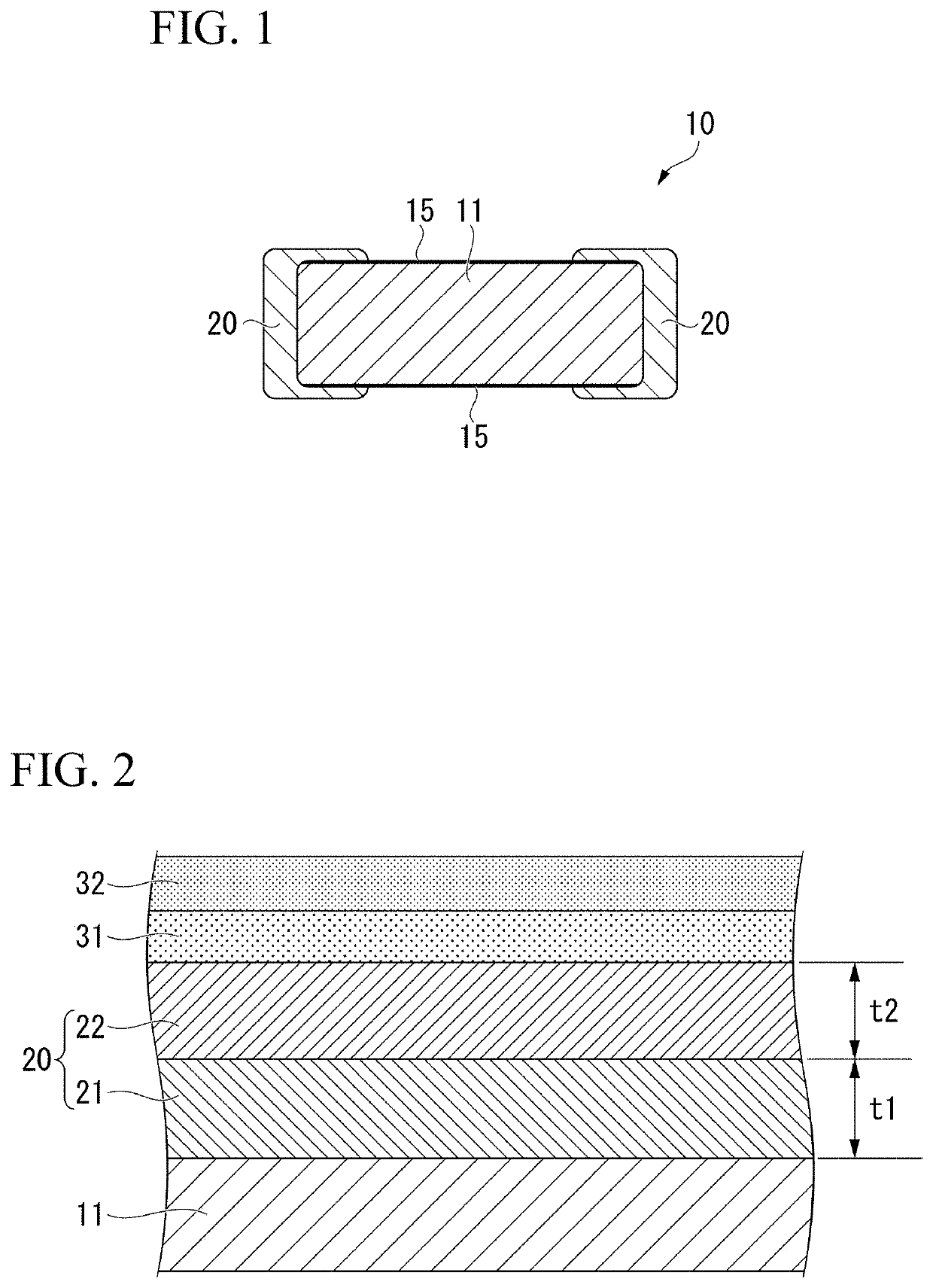
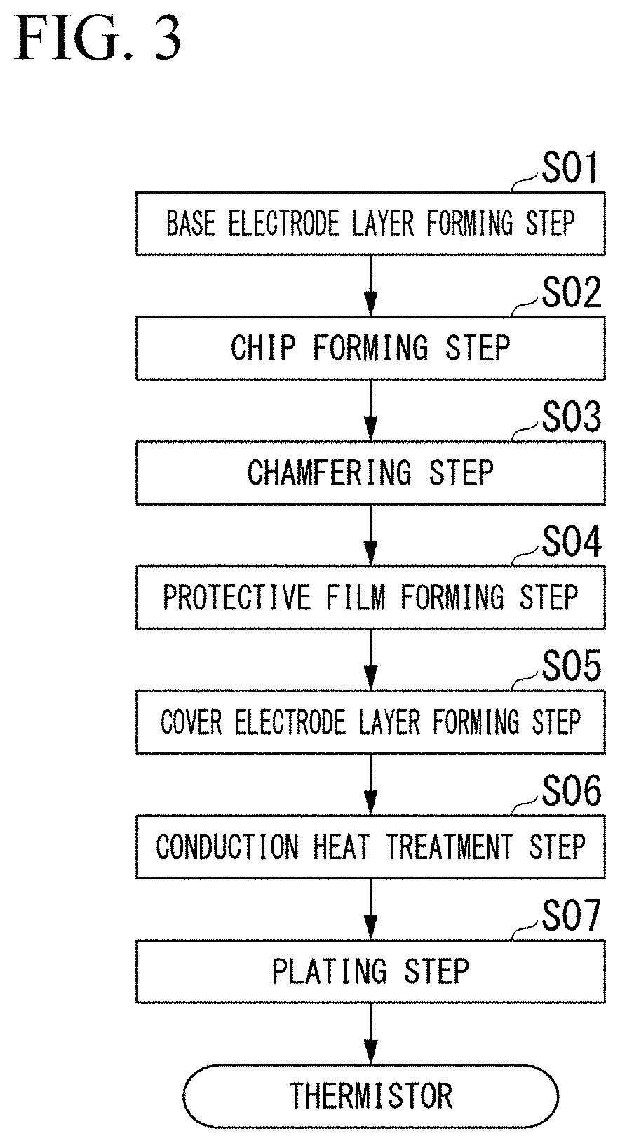
[0084]An ethanol dispersion solution of RuO2 powder was spin-applied to both surfaces of a thermistor wafer of 38×55 mm and 0.36 mm thickness, and, after baking at 250° C., a conductive oxide layer was formed.

[0085]Next, the base electrode layer was formed on the surface of the conductive oxide layer by printing by screen printing and baking a conductive paste including Ag powder and glass powder (weight ratio, Ag:glass=9:1).

[0086]The thermistor wafer with the base electrode layer formed as described above was cut into 0.18 mm squares by dicing to form chips.

[0087]After the chips were formed, chamfering was carried out by barrel processing.

[0088]After the chamfering, the thermistor chip was placed in a water-ethanol mixed solvent and 5.2 g of ethyl orthosilicate and 16.6 g of NaOH aqueous solution (0.2 mol / L) were added thereto while stirring to form a protec...


PUM


Abstract

The present invention is provided with a base electrode layer forming step of forming a base electrode layer on both surfaces of a thermistor wafer formed of a thermistor material, a chip forming step of obtaining a thermistor chip with a base electrode layer by cutting the thermistor wafer to form chips, a protective film forming step of forming a protective film formed of an oxide on an entire surface of the thermistor chip with a base electrode layer, a cover electrode layer forming step of forming a cover electrode layer by applying and sintering a conductive paste on an end surface of the thermistor chip with a base electrode layer, and a conduction heat treatment step of performing a heat treatment such that the base electrode layer and the cover electrode layer are electrically conductive, in which the electrode portion is formed.

Description

TECHNICAL FIELD[0001]This invention relates to a method of manufacturing a thermistor, which includes a thermistor chip formed of a thermistor material, a protective film formed on a surface of the thermistor chip, and electrode portions formed on each of both end portions of the thermistor chip.[0002]Priority is claimed on Japanese Patent Application No. 2019-030527, filed in Japan on Feb. 22, 2019, the content of which is incorporated herein by reference.BACKGROUND ART[0003]The thermistor (thermistor material) described above has a characteristic by which the electrical resistance thereof changes according to the temperature and is applied in the temperature compensation of various electronic devices, in temperature sensors, and the like. In particular, recently, chip-type thermistors mounted on circuit boards have been widely used.[0004]The thermistor described above has a structure formed of a thermistor chip and a pair of electrode portions at both ends of the thermistor chip.[...

Claims


Application Information

Patent Timeline
IPC IPC(8): H01C7/00H01C17/00H01C17/065H01C1/142
CPCH01C7/008H01C1/142H01C17/06553H01C17/006H01C1/148H01C1/028H01C17/02H01C17/283H01C17/281
Inventor YONEZAWA, TAKEHIROHIGANO, SATOKO
Owner MITSUBISHI MATERIALS CORP
Why Eureka
Try Eureka